S0709730K
Page 5
Power Steering Unit
Return to Master Table of Contents
Neutral Operation
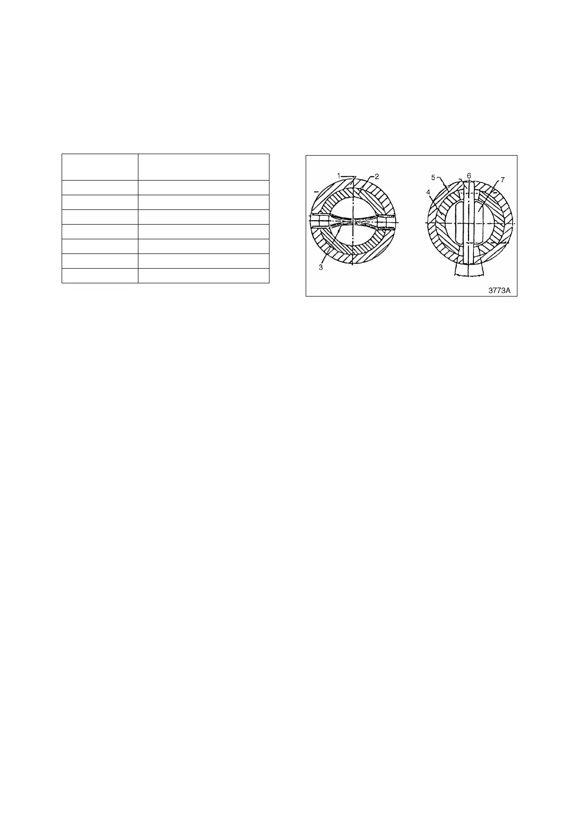
With the steering wheel in the neutral position (wheels turned neither right nor left), the spool (2, Figure 3)
and sleeve (1) are stationary at the position where the center pin (6) becomes centered in the spool space
by the centering springs (3). Oil flow through the load sensing line (LS), port L, port R, and port T are
bypassed to the tank line and the oil supply (P) is blocked by the directional spool in the steering unit (1,
Figure 2). Even if an external force is applied to the steering cylinder, the steering unit is protected because
the oil path is blocked by the directional spool.
Right Turn
The spool (2, Figure 3) is engaged with the spline of the steering shaft. When the steering wheel is turned
to the right, the spool turns. The sleeve (1) is connected to the spool (2) by centering springs (3). When
spool turns, the sleeve turns. The sleeve turning angle is about 10° less than the spool turning angle. This
allows the longitudinal slots in the spool to align with the ports in the sleeve. Oil from port P on the steering
unit (1, Figure 2) travels through the control spool and is directed to port R which directs the oil to the
steering cylinders (3, Figure 2). The amount of flow metered to port R is controlled by the amount of
steering wheel rotation. Excess oil flow through port P that is not metered to port R, is directed by the spool
to port T and is then directed through the il cooler and into the tank.
Left Turn
The spool (2, Figure 3) is engaged with the spline of the steering shaft. When the steering wheel is
connected to the spool (2) by centering springs (3). When the spool turns, the sleeve turns. The sleeve
turning angle is about 10° less than the spool turning angle. This allows the longitudinal slots in the spool to
align with the ports in the sleeve. When the steering wheel is turned to the left, oil from port P on the
steering unit (1, Figure 2) is directed through the control spool in the steering unit, out port L and into the
steering cylinders (3, Figure 2). The amount of oil flow metered to port L is controlled by the amount of
steering wheel rotation. Excess oil flow through port P that is not metered to port L, is directed by the spool
to port T and is then directed through the oil cooler and into the tank.
GEROTOR OPERATION
If the engine or pump is not operating, the steering unit (1, Figure 2) works as a manual pump when the
steering wheel is turned. The gerotor will work when the input torque to the steering wheel is less than 12
kg•m (87 ft lb). If the necessary input torque is greater than this, the gerotor will not function. When the
steering wheel is turned, the gerotor creates a vacuum that draws oil from port T. See Figure 2. The gerotor
pumps this oil through the control spool and into the steering cylinders. Return oil flows back to the spool
and is used to lubricate the steering unit (1, Figure 2). The return oil then flows back into the tank line and
is recirculated back to the gerotor and the steering cylinders.
Reference
Number
Description
1 Sleeve
2 Spool
3 Centering Spring
4 Spool
5 Sleeve
6 Center Pin
7 Drive shaft
Figure 3