S0709750K
Page 3
Restriction Valve
Return to Master Table of Contents
GENERAL DESCRIPTION
THEORY OF OPERATION
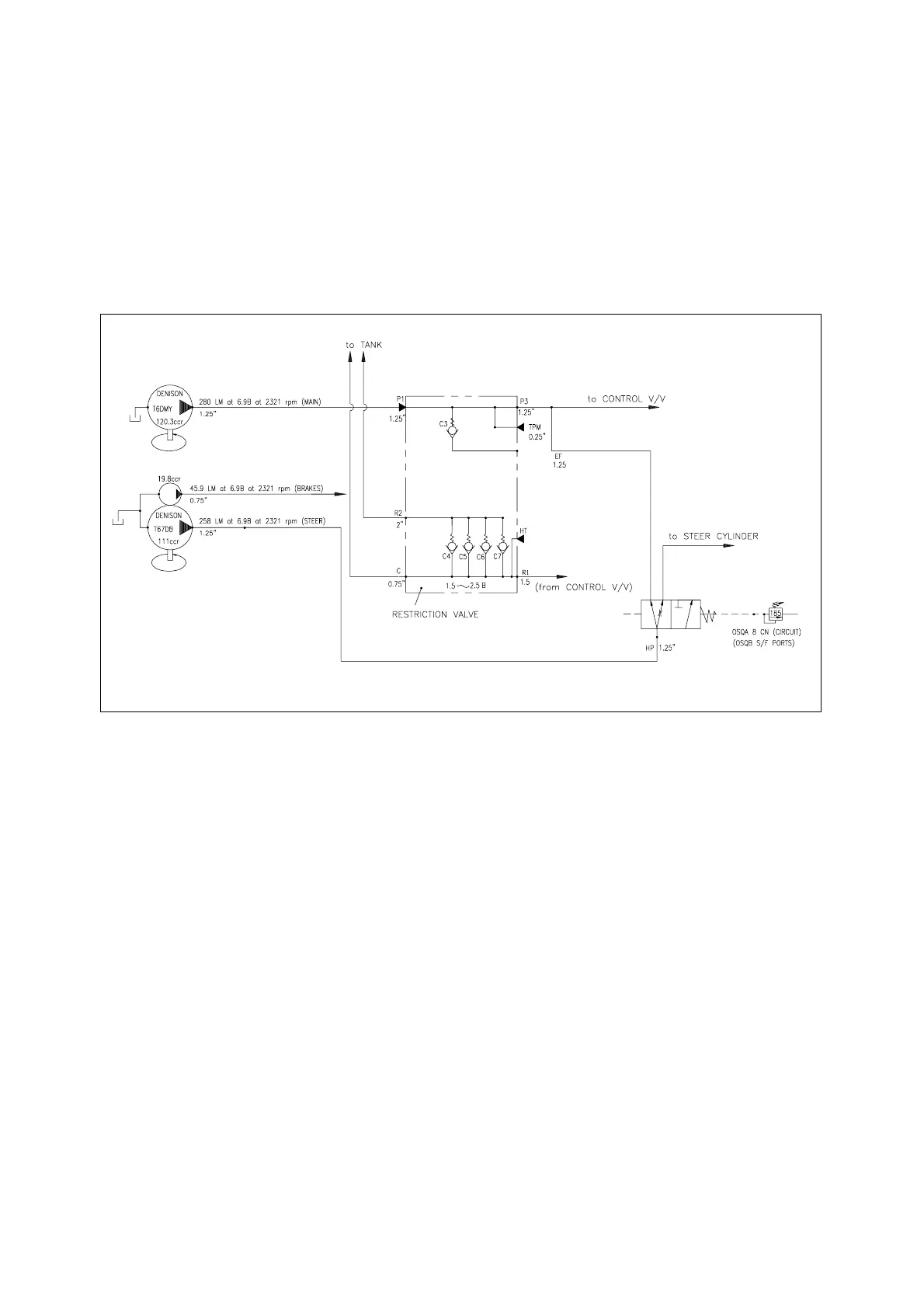
The restriction valve is made up of one cartridge C1 and four bypass check valves C2, C3, C4, and C5.
Output from the steering pump passes through the priority valve that is part of the flow amplifier. See the
hydraulic schematic (Figure 1). This flow then passes out of the flow amplifier and enters the restriction
valve at port EF. This allows output from the steering pump to join flow from the main pump to supply the
boom, bucket and option control valves.
AHS3820L
Figure 1 RESTRICTION CIRCUIT