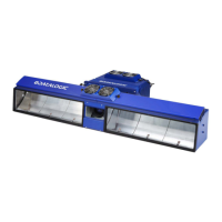
E-GENIUS
RangeFinder Settings
These values are entered by the Wizard.
For information RangeFinder installation and calibration, see section 5.2.2
Enter the offset on the X axis (across the conveyor) of the RangeFinder. This
parameter compensates for the RangeFinder not being centered above the
scanning surface.
Enter the height that the RangeFinder is mounted above the scanning surface (Z
axis)
Enter the usable area on left side of the RangeFinder. This is referenced from the
center of the RangeFinder. Any codewords that are beyond the dimension set in
this field will be ignored.
Enter the usable area on right side of the RangeFinder. This is referenced from
the center of the RangeFinder. Any codewords that are beyond the dimension set
in this field will be ignored.
Offset to
RangeFinder
Gain Setting
This parameter adjusts the gain value used by the Rangefinder. This is an offset
that is applied to the “Factory Gain Setting”. This value can be positive or
negative. See Setting the RangeFinder Gain in section 5.2.2.
Delay Distance
(for Object
Filtering)
This specifies the “delay” in transmitting the Rangefinder focus data. The size of
this delay helps with the ‘bounding’ of boxes to smooth the data for the sides.
Essentially the range used in the ‘bounding’ is about 25 mm [1 in] less than twice
this number (in other words, if left at 70 mm [3 in], bounding is performed over
approximately 127 mm [5 in]).
This value cannot be smaller than the minimum box size (minimum box size will
be used in that case). It cannot be larger than 200 mm [8 in].
Package
Detection
Debounce
This specifies the “Distance without height data” that must be observed before the
package detection algorithm terminates a box.
Be careful making this value much larger, as that will increase the sensitivity of the
rangefinder to “belt noise”.
Enable Rough
Dimensioning
Select the check box to allow the RangeFinder to return rough package
dimensions.
Photo Sensor
Indicates
Package is
Present
Select the check box to allow the RangeFinder to indicate package is present.
Select 0 or 180 from the drop-down list. This identifies the RangeFinder mount as
Standard or Non-Standard.
The Yaw should either be 0 or 180, 0 being the standard mount where the two
indicator laser dots are upstream from the RangeFinder scan line. When set to
180-degrees, the two indicator laser dots are downstream from the RangeFinder
scan line
Transmit Point
Reference Edge
Select Leading Edge or Trailing Edge from the drop-down list to reference the
leading or trailing edge of the package.
Distance to
Transmit Point
Enter the distance from the location of the trigger source to the host transmit point
in the field provided.

 Loading...