AV7000 LINEAR CAMERA REFERENCE MANUAL
between the two units. The operator obtains information relative to the light grid status and
error conditions through LEDs located on the device and/or through the control interface of a
remote PC.
Mounting the DS2 Light Array
The emitter and receiver units have to be mounted with the relevant sensitive surfaces facing
each other. The connectors must be positioned on the same side and with the operating
distance of the model used (see DS2 Instruction Manual available at www.datalogic.com).
Reference system application drawings for proper placement.
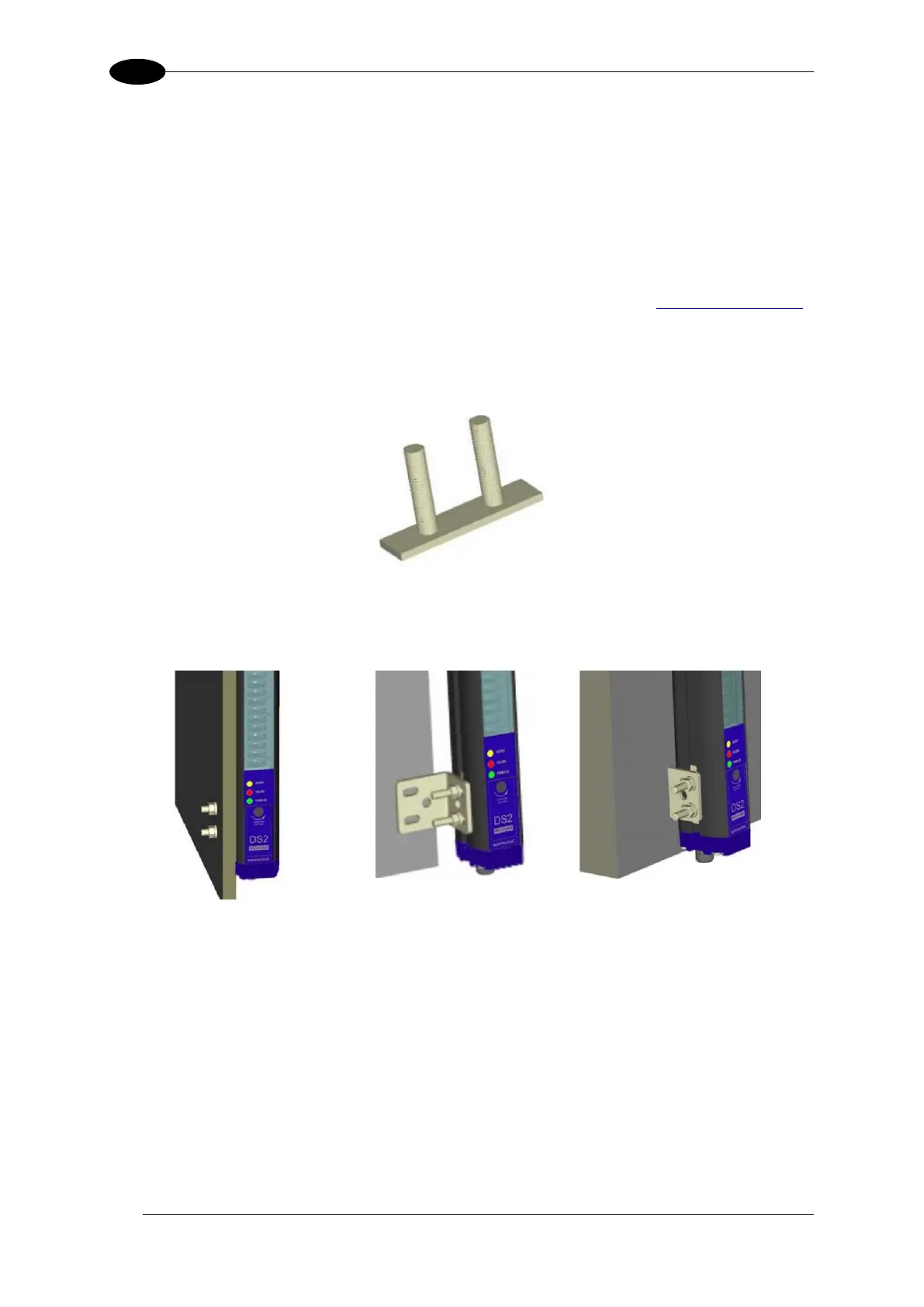
The two units must be aligned and parallel as much as possible. To mount the device, insert
the threaded pins supplied (shown below) in the slots present on the two units.
Figure 113: Threaded pins
Depending on the particular application and/or type of support, the operator can use the
fixing pins or the rigid fixing brackets supplied to mount the two units as shown below.
Figure 114: Threaded pins

 Loading...

