MECHANICAL INSTALLATION
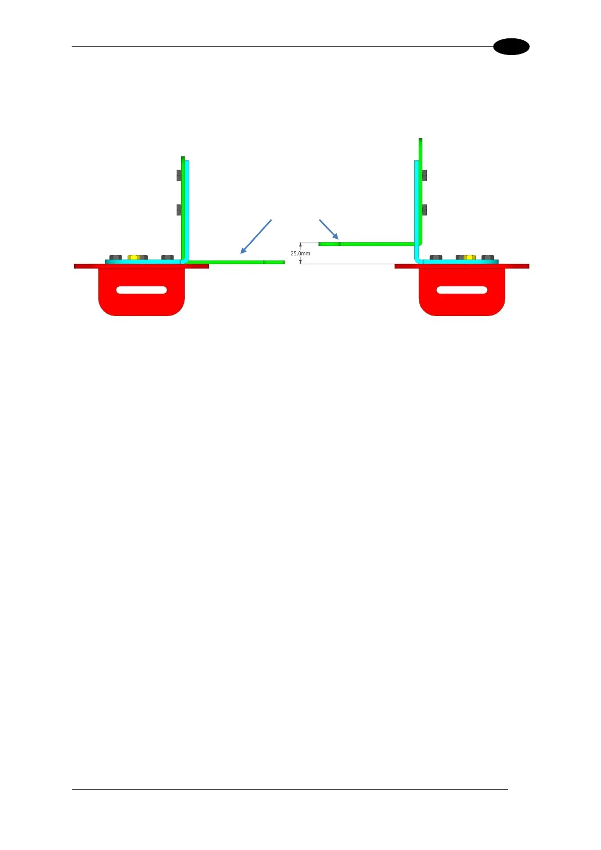
Although both brackets will be mounted having 25 mm [1 in] between the Support Bracket
(green) surface and the Rising Bracket (red) surface, for mounting purposes the "top"
bracket should be pre-assembled so that this distance is 0 mm/in. This will provide clearance
when placing the camera/illuminator between the mounted brackets.
Figure 30: Side Bracket Assembly, Support Bracket position

 Loading...

