4-28 Service Manual
WARNING: When replacing the LVPS card assembly, ensure that the voltage selection switch is set to the
proper setting, or damage will occur.
1. Remove the door assembly, rear. Go to “Door assembly, rear removal” on page 4-14.
3. Disconnect the connector (A) from the LVPS card assembly.
4. Remove the two screws (B) from the LVPS card assembly.
5. Gently pull the LVPS card assembly from the machine.
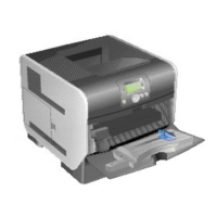
LVPS card assembly removal (5230n/dn)
2. Remove the side cover, right. Go to “Side cover, right removal (5230n/dn)” on page 4-67.