Doosan Robotics User Manual v2.6.1
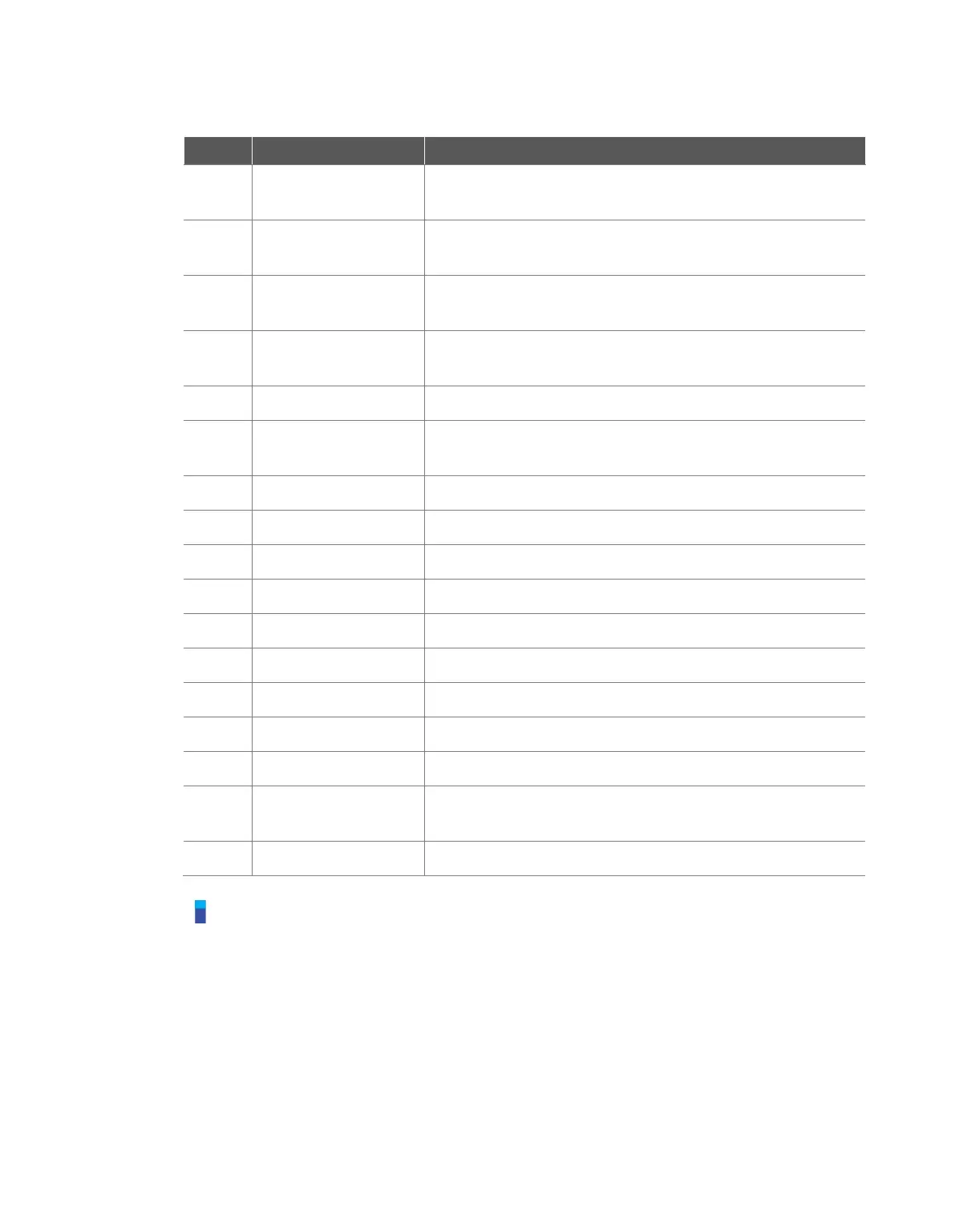
It is the tab that displays monitoring information necessary for
executing the input signal and Task of Smart Pendant.
It is the tab that displays the log messages collected during task
execution.
Smart Pendant Enable
Signal
When the Smart Pendant is connected to the controller, it is
displayed as Checked (green).
When the homming button of the Smart Pendant is pressed, the
indicator is displayed as Checked (green).
Displays the Servo On/Off status
Indicators of P1-P4 press status
Area displaying the task to be used by the Smart Pendant
Average play time of each task cycle
TCP information used by the current task
Tool Weight information used by the current task
Tool Shape information used by the current task
Collision threshold information
Digital / Flange I/O
information
Digital / Flange I/O information
Button to close the Smart Pendant mode.
Note
If the Emergency Stop or Protective Stop occurs in Smart Pendant Mode, it is handled as follows:
1. Emergency Stop: An emergency stop popup is displayed. After removing the cause of
emergency stop - pulling or twist the emergency stop switch for reset, the popup closes
automatically.
2. Protective Stop causing the transition to Servo Off state: A red protective stop popup is
displayed. If the Smart Pendant’s Servo On button is pushed after removing the cause of
protective stop, the robot servo drives turn on and the popup closes automatically.
3. Protective Stop causing the transition to Interrupted state: A yellow protective stop popup is
displayed. If Smart Pendant’s Reset button is pushed after removing the cause of protective
stop, the robot state chages to normal standby state – Manual Standby, Auto Standby, or HGC