CHAPTER 7: PROTECTION GROUPED PROTECTION ELEMENTS
D90
PLUS
LINE DISTANCE PROTECTION SYSTEM – INSTRUCTION MANUAL 247
Block
Range: any FlexLogic operand or shared operand
Default: Off
Assertion of the operand assigned to this setting blocks operation of the neutral
instantaneous overcurrent element.
Events
Range: Enabled, Disabled
Default: varies with UR
Plus
-series model; see the EnerVista UR
Plus
Setup software
This setting enables and disables the logging of neutral instantaneous overcurrent
events in the sequence of events recorder.
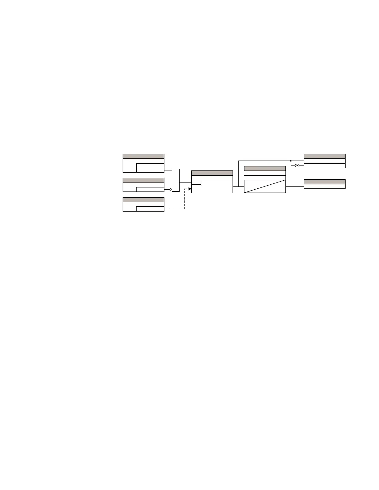
The figure shows the logic for the neutral instantaneous overcurrent 1 element. The logic is
identical for all neutral instantaneous overcurrent elements.
Figure 212: Neutral instantaneous overcurrent 1 scheme logic
Neutral directional overcurrent
There are two neutral directional overcurrent protection elements available. The element
provides both forward and reverse fault direction indications the NEUTRAL DIR OC1 FWD and
NEUTRAL DIR OC1 REV operands, respectively. The output operand is asserted if the
magnitude of the operating current is above a pickup level (overcurrent unit) and the fault
direction is seen as forward or reverse, respectively (directional unit).
The overcurrent unit responds to the magnitude of a fundamental frequency phasor of
either the neutral current calculated from the phase currents or the ground current. There
are separate pickup settings for the forward-looking and reverse-looking functions. If set
to use the calculated 3I_0, the element applies a positive-sequence restraint for better
performance: a small user-programmable portion of the positive–sequence current
magnitude is subtracted from the zero-sequence current magnitude when forming the
operating quantity.
Eq. 25
The positive-sequence restraint allows for more sensitive settings by counterbalancing
spurious zero-sequence currents resulting from
• System unbalances under heavy load conditions
• Transformation errors of current transformers (CTs) during double-line and three-
phase faults
• Switch-off transients during double-line and three-phase faults
The positive-sequence restraint must be considered when testing for pickup accuracy and
response time (multiple of pickup). The operating quantity depends on the way the test
currents are injected into the relay. For single-phase injection, the operating quantity is
Eq. 26
For three-phase pure zero-sequence injection, the operating quantity is
Eq. 27
$1'
$&'5
6(77,1*
'LVDEOHG
(QDEOHG
)XQFWLRQ
6(77,1*
2II
%ORFN
6(77,1*
,B
6RXUFH
î_B_² î_B_ 3LFNXS,.,
6(77,1*
3LFNXS
581
6(77,1*
3LFNXS'HOD\
7
3.3
7
567
5HVHW'HOD\
)/(;/2*,&23(5$1'6
1(875$/,2&3.3
1(875$/,2&'32
)/(;/2*,&23(5$1'
1(875$/,2&23
, , . ,
RS
î_ B_² î_ B_
,.,
RS LQMHFWHG
² î