248 D90
PLUS
LINE DISTANCE PROTECTION SYSTEM – INSTRUCTION MANUAL
GROUPED PROTECTION ELEMENTS CHAPTER 7: PROTECTION
The positive-sequence restraint is removed for low currents. If the positive-sequence
current is below 0.8 pu, the restraint is removed by changing the constant K to zero. This
facilitates better response to high-resistance faults when the unbalance is very small and
there is no danger of excessive CT errors as the current is low.
The directional unit uses the zero-sequence current (I_0) or ground current (IG) for fault
direction discrimination and can be programmed to use either zero-sequence voltage
(“Calculated V0” or “Measured VX”), ground current (IG), or both for polarizing. The phasors
for the neutral directional overcurrent element directional unit are described below, where
V_0 is the zero-sequence voltage, I_0 is the zero-sequence current, ECA is the element
characteristic angle, IG is the ground current, and
Eq. 28
Eq. 29
Table 14: Phasors for “Calculated 3I_0” configuration
The operating current for overcurrent unit for the “Calculated 3I_0” configuration is
Eq. 30
Table 15: Phasors for “Measured IG” configuration
The operating current for overcurrent unit for the “Measured IG” configuration is
Eq. 31
When the Polarizing Voltage setting is programmed as “Measured VX,” one-third of this
voltage is used in place of V_0. The following figure explains the usage of the voltage
polarized directional unit of the element.
The figure shows the voltage-polarized phase angle comparator characteristics for a
phase A to ground fault, with the element characteristic angle equal to 90° (center line of
operating characteristic), forward limit angle equal to 80° (the ± angular limit with the ECA
for operation), and reverse limit angle equal to 80° (the ± angular limit with the ECA for
operation).
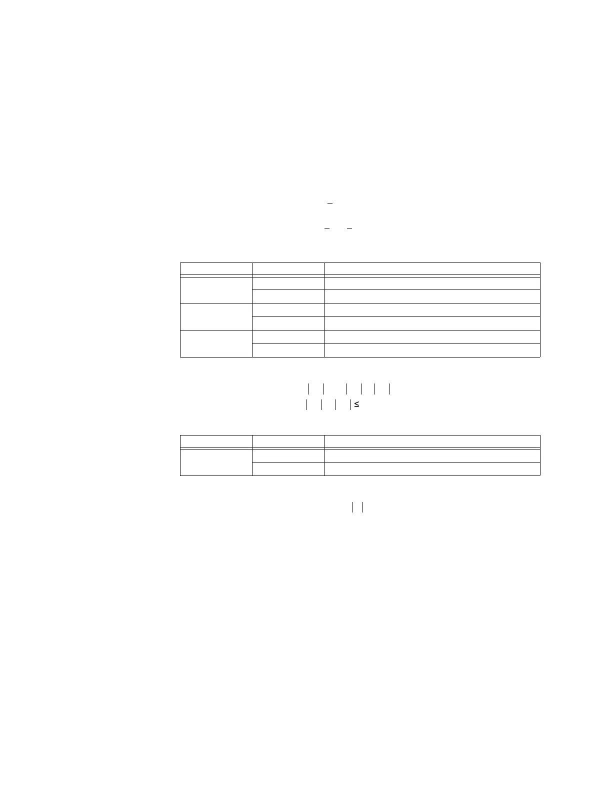
Polarizing mode Direction Compared phasors
Voltage Forward –V_0 + Z_offset × I_0 and I_0 × 1∠ECA
Reverse –V_0+Z_offset×–I_0 and I_0×1∠ECA
Current Forward IG and I_0
Reverse IG and –I_0
Dual Forward –V_0 + Z_offset × I_0 and I_0 × 1∠ECA or IG and I_0
Reverse –V_0+Z_offset×I_0 and I_0×1∠ECA or IG and –I_0
Polarizing mode Direction Compared phasors
Voltage Forward –V_0 + Z_offset × IG/3 and IG × 1∠ECA
Reverse –V_0+Z_offset×–IG/3 and –IG×1∠ECA
SX
B
LI
B
SXB
LI
BB
î
!î²î
,,,
,,.,,
RS
RS