268 D90
PLUS
LINE DISTANCE PROTECTION SYSTEM – INSTRUCTION MANUAL
GROUPED PROTECTION ELEMENTS CHAPTER 7: PROTECTION
PHASE UV1 OP.............................................
Asserted when at least one phase of the phase undervoltage 1
element operates.
PHASE UV1 OP A ........................................
Asserted when phase A of the phase undervoltage 1 element
operates.
PHASE UV1 OP B ........................................
Asserted when phase B of the phase undervoltage 1 element
operates.
PHASE UV1 OP C ........................................
Asserted when phase C of the phase undervoltage 1 element
operates.
PHASE UV1 PKP ..........................................
Asserted when at least one phase of the phase undervoltage 1
element picks up.
PHASE UV1 PKP A ......................................
Asserted when phase A of the phase undervoltage 1 element
picks up.
PHASE UV1 PKP B ......................................
Asserted when phase B of the phase undervoltage 1 element
picks up.
PHASE UV1 PKP C ......................................
Asserted when phase C of the phase undervoltage 1 element
picks up.
PHASE UV2....................................................
Same set of operands as shown above for the phase
undervoltage 2 element.
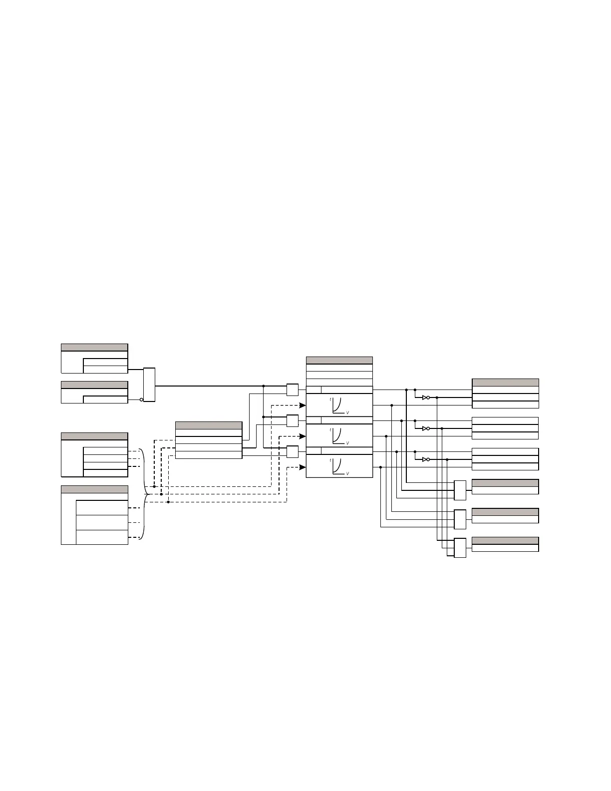
The figure shows the logic for the phase undervoltage 1 element. The logic is similar for all
phase undervoltage elements.
Figure 229: Phase undervoltage 1 logic
Phase overvoltage
The phase overvoltage element can be used as an instantaneous element with no
intentional time delay or as a definite time element. The input voltage is the phase-to-
phase voltage, either measured directly from delta-connected VTs or as calculated from
phase-to-ground (wye) connected VTs. The specific voltages to be used for each phase are
shown in the logic diagram.
Select the Settings > Protection > Elements > Group 1 > Voltage > Phase OV menu to
open the phase overvoltage configuration window.
$&'5
$1'
$1'
$1'
25
25
$1'
$1'
6(77,1*
'LVDEOHG
(QDEOHG
)XQFWLRQ
6(77,1*
2II
%ORFN
6(77,1*
97 'HOWD9$%
97 'HOWD9%&
6RXUFH
97 'HOWD9&$
97 :\H
6(77,1*
9$*SKDVHWRJURXQG
9$%SKDVHWRSKDVH
0RGH
9%*SKDVHWRJURXQG
9%&SKDVHWRSKDVH
9&*SKDVHWRJURXQG
9&$SKDVHWRSKDVH
6(77,1*
9$*RU9$* 0LQLPXP
9%*RU9%& 0LQLPXP
0LQLPXP9ROWDJH
9&*RU9&$0LQLPXP
6(77,1*
'HOD\
581
9$*RU9$% 3LFNXS
581
9%*RU9%& 3LFNXS
581
9&*RU9&$ 3LFNXS
&XUYH
3LFNXS
)/(;/2*,&23(5$1'6
3+$6(893.3$
3+$6(89'32$
3+$6(8923$
3+$6(893.3%
3+$6(89'32%
3+$6(8923%
3+$6(893.3&
3+$6(89'32&
3+$6(8923&
)/(;/2*,&23(5$1'
3+$6(893.3
)/(;/2*,&23(5$1'
3+$6(8923
)/(;/2*,&23(5$1'
3+$6(89'32