CHAPTER 7: PROTECTION GROUPED PROTECTION ELEMENTS
D90
PLUS
LINE DISTANCE PROTECTION SYSTEM – INSTRUCTION MANUAL 269
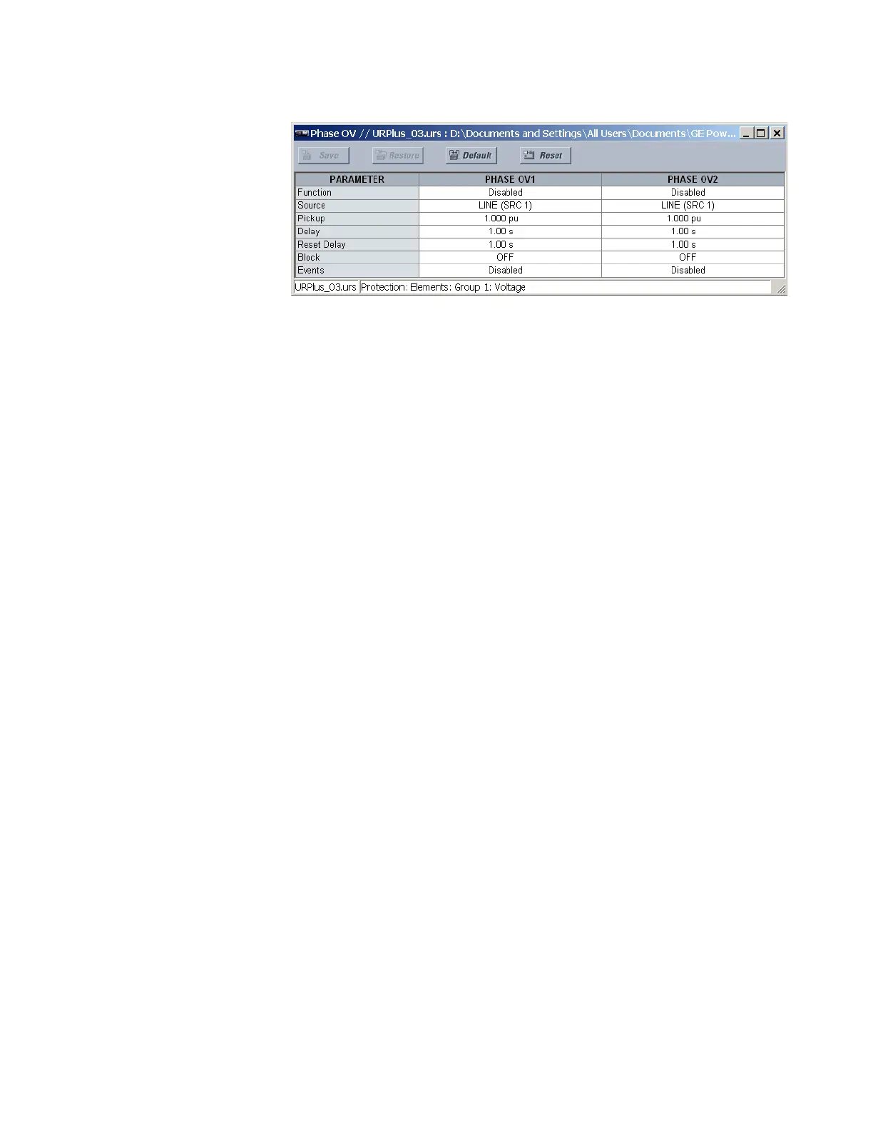
Figure 230: Phase overvoltage configuration settings
The following settings are available for each phase overvoltage element.
Function
Range: Enabled, Disabled
Default: Disabled
This setting enables and disables the phase overvoltage protection element.
Source
Range: LINE (SRC 1), BKR 1 (SRC 2), BKR 2 (SRC 3)
Default: LINE (SRC 1)
This setting selects the signal source for the phase overvoltage protection element.
Pickup
Range: 0.000 to 3.000 pu in steps of 0.001
Default: 1.000 pu
This setting specifies the phase overvoltage pickup level in per-unit values.
Delay
Range: 0.00 to 600.00 seconds in steps of 0.01
Default: 1.00 seconds
This setting specifies the minimum operating time of the phase overvoltage element.
Reset Delay
Range: 0.00 to 600.00 seconds in steps of 0.01
Default: 1.00 seconds
This setting specifies the minimum reset time of the phase overvoltage element.
Block
Range: any FlexLogic operand or shared operand
Default: Off
Assertion of the operand assigned to this setting blocks the phase overvoltage element.
Events
Range: Enabled, Disabled
Default: Disabled
This setting enables and disables the logging of phase overvoltage events in the
sequence of events recorder.
The figure shows the logic for the phase overvoltage 1 element. The logic is similar for all
phase overvoltage elements.