CHAPTER 7: PROTECTION GROUPED PROTECTION ELEMENTS
D90
PLUS
LINE DISTANCE PROTECTION SYSTEM – INSTRUCTION MANUAL 273
Events
Range: Enabled, Disabled
Default: Disabled
This setting enables and disables the logging of negative-sequence overvoltage events
in the sequence of events recorder.
The figure shows the logic for the negative-sequence overvoltage 1 element. The logic is
similar for all negative-sequence overvoltage elements.
Figure 235: Negative-sequence overvoltage logic
Auxiliary undervoltage
The auxiliary undervoltage element is intended for monitoring undervoltage conditions of
the auxiliary voltage. The element pickup selects the voltage level at which the time
undervoltage element starts timing. The nominal secondary voltage of the auxiliary
voltage channel entered for the
Auxiliary VT Secondary setting is the per-unit base used
when setting the pickup level.
Both the
Pickup and Delay settings establish the operating curve of the undervoltage
element. The auxiliary undervoltage element can be programmed to use either definite
time delay or inverse time delay characteristics.
The auxiliary undervoltage element resets instantaneously.
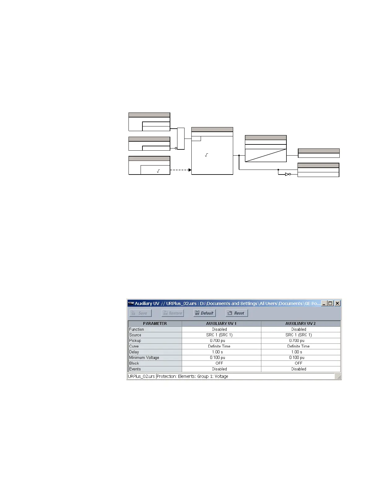
Select the Settings > Protection > Elements > Group 1 > Voltage > Auxiliary UV menu to
open the auxiliary undervoltage configuration window.
Figure 236: Auxiliary undervoltage configuration settings
The following settings are available for each auxiliary undervoltage element.
Function
Range: Enabled, Disabled
Default: Disabled
This setting enables and disables the auxiliary undervoltage protection element.
$&'5
$1'
6(77,1*
'LVDEOHG
(QDEOHG
)XQFWLRQ
6(77,1*
2II
%ORFN
6(77,1*
6RXUFH
97 :\H9B
97 'HOWDî9B
9BRUî9B 3LFNXS
6(77,1*
3LFNXS
581
3LFNXS'HOD\
6(77,1*6
7
3.3
7
567
5HVHW'HOD\
)/(;/2*,&23(5$1'6
1(*6(42923
1(*6(4293.3
1(*6(429'32
)/(;/2*,&23(5$1'