272 D90
PLUS
LINE DISTANCE PROTECTION SYSTEM – INSTRUCTION MANUAL
GROUPED PROTECTION ELEMENTS CHAPTER 7: PROTECTION
Negative-sequence overvoltage
The negative-sequence overvoltage element can be used to detect loss of one or two
phases of the source, a reversed phase sequence of voltage, or a non-symmetrical system
voltage condition.
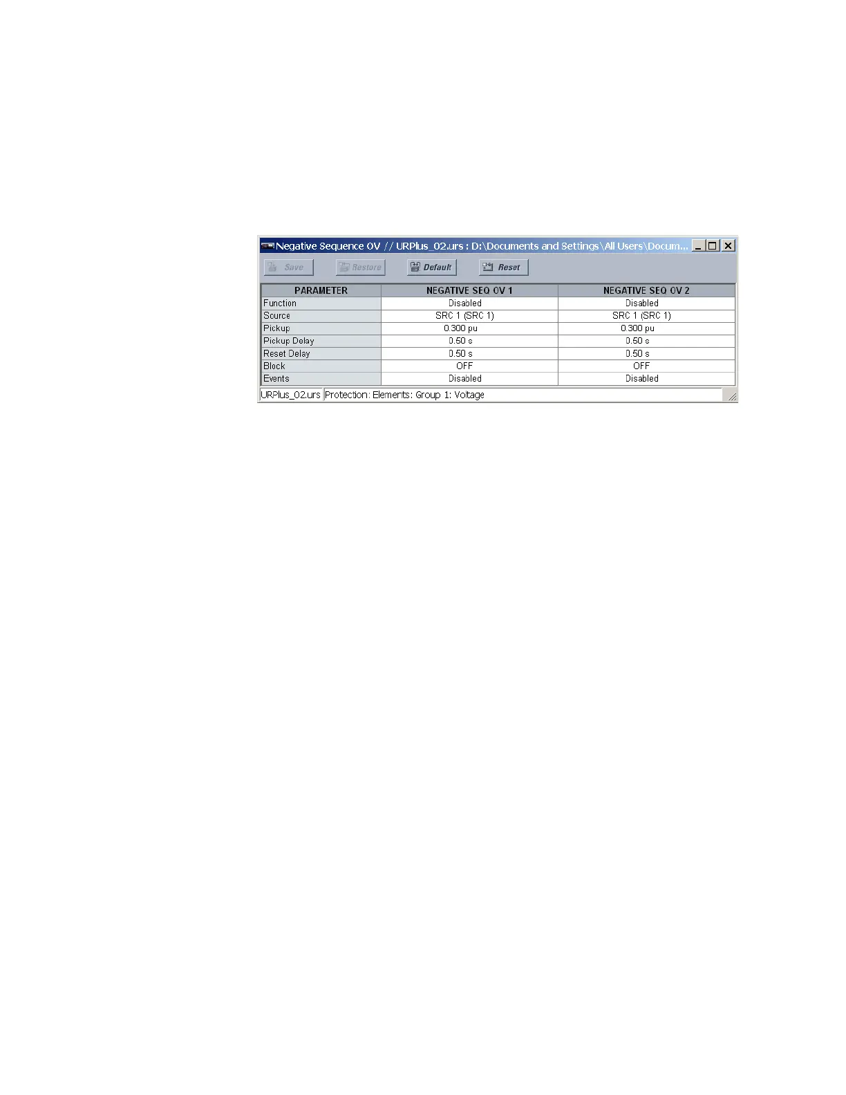
Select the Settings > Protection > Elements > Group 1 > Voltage > Negative Sequence
OV menu to open the negative-sequence overvoltage configuration window.
Figure 234: Negative-sequence overvoltage configuration settings
The following settings are available for each negative-sequence overvoltage element.
Function
Range: Enabled, Disabled
Default: Disabled
This setting enables and disables the negative-sequence overvoltage protection
element.
Source
Range: LINE (SRC 1), BKR 1 (SRC 2), BKR 2 (SRC 3)
Default: LINE (SRC 1)
This setting selects the signal source for the negative-sequence overvoltage protection
element.
Pickup
Range: 0.000 to 1.250 pu in steps of 0.001
Default: 1.000 pu
This setting specifies the negative-sequence overvoltage pickup level in per-unit values.
Pickup Delay
Range: 0.00 to 600.00 seconds in steps of 0.01
Default: 1.00 seconds
This setting specifies the minimum operating time of the negative-sequence overvoltage
element.
Reset Delay
Range: 0.00 to 600.00 seconds in steps of 0.01
Default: 1.00 seconds
This setting specifies the minimum reset time of the negative-sequence overvoltage
element.
Block
Range: any FlexLogic operand or shared operand
Default: Off
Assertion of the operand assigned to this setting blocks the negative-sequence
overvoltage element.