54 D90
PLUS
LINE DISTANCE PROTECTION SYSTEM – INSTRUCTION MANUAL
WIRING CHAPTER 3: INSTALLATION
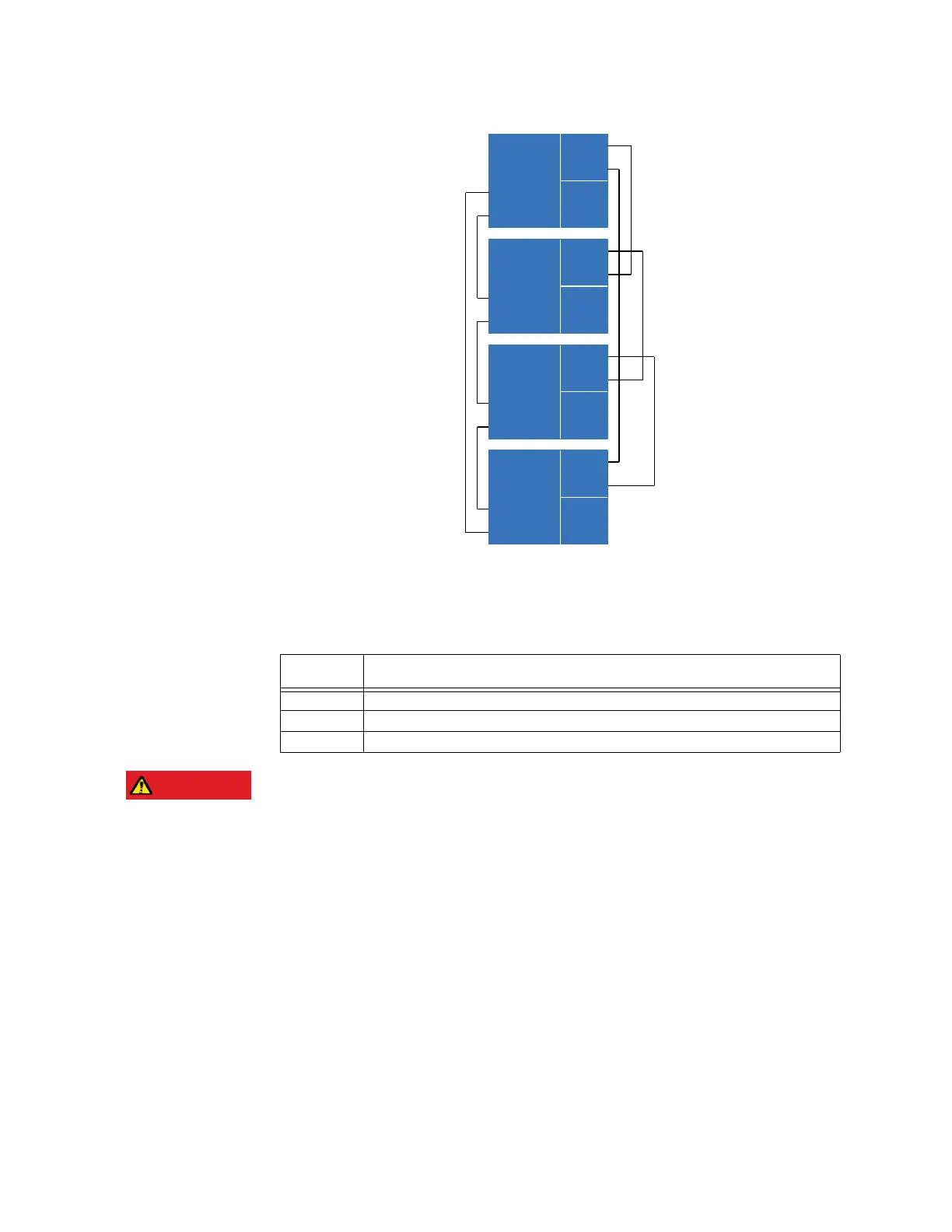
Figure 29: Direct input and output dual channel connection
The interconnection requirements are described in further detail in this section for each
inter-relay communication module, which is specified at the time of ordering. The table
lists these modules. All fiber modules use ST type connectors.
Table 3: Inter-relay communication modules
DANGER:
The 850 nm module uses a class 1 VCSEL laser that is harmful to the eye. Observing any
fiber transmitter output can cause serious injury to the eye.
Direct input and output link LEDs
The link LEDs for channels 1 and 2 are located on the rear of the inter-relay
communications card, which is located in slot B.
Order code
option
Specification
B G.703, 64/128 kbps, two channels
C RS422, 64/128 kbps, two channels, two clock inputs
D 850 nm, 64/128 kbps, ST multimode laser, two channels with DDMI
$&'5
7[
853OXV
7[
5[
5[
7[
853OXV
7[
5[
5[
7[
853OXV
7[
5[
5[
7[
853OXV
7[
5[
5[