CHAPTER 3: INSTALLATION WIRING
D90
PLUS
LINE DISTANCE PROTECTION SYSTEM – INSTRUCTION MANUAL 55
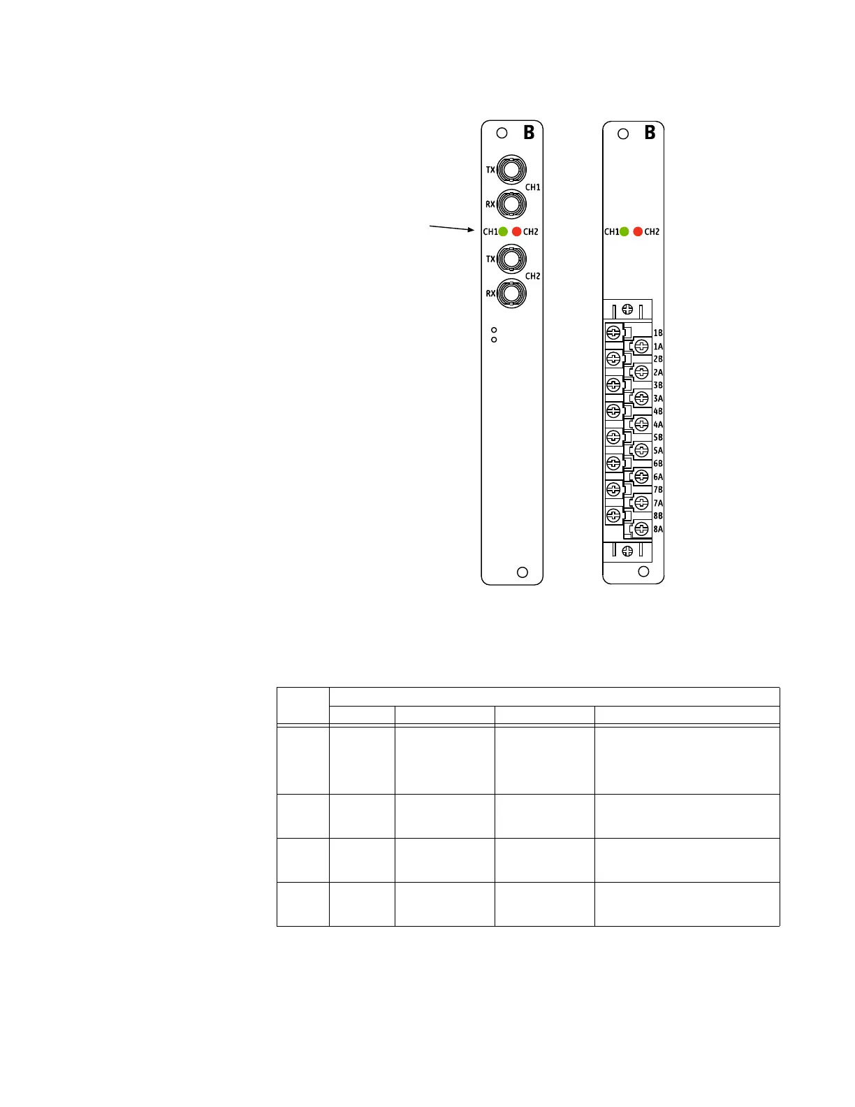
Figure 30: Link LEDs for fiber, RS422, and G.703 modules
The table describes the operation of the link LEDs.
Table 4: Link LED operation
Protocol LED indications
Red, solid Green, solid Green, blinking Yellow, blinking
IEEE
C37.94
Loss of
signal
Signal detected,
but not receiving
valid data
Signal detected
and receiving valid
data; yellow bit
alarm not set
Signal detected, receiving valid
data and the received yellow bit
alarm is set; the yellow bit indicates
that remote unit is not receiving
valid data
Direct
fiber
Loss of
signal
Signal detected,
but not receiving
valid data
Signal detected
and receiving valid
data
Not used
G.703 Loss of
signal
Signal detected,
but not receiving
valid data
Signal detected
and receiving valid
data
Not used
RS422 Loss of
clock
Clock detected,
but not receiving
valid data
Clock detected
and receiving valid
data
Not used
)LEHUPRGXOH 56DQG*
PRGXOH
$&'5
/LQN/('V