CHAPTER 15: THEORY OF OPERATION DISTANCE ELEMENTS
D90
PLUS
LINE DISTANCE PROTECTION SYSTEM – INSTRUCTION MANUAL 631
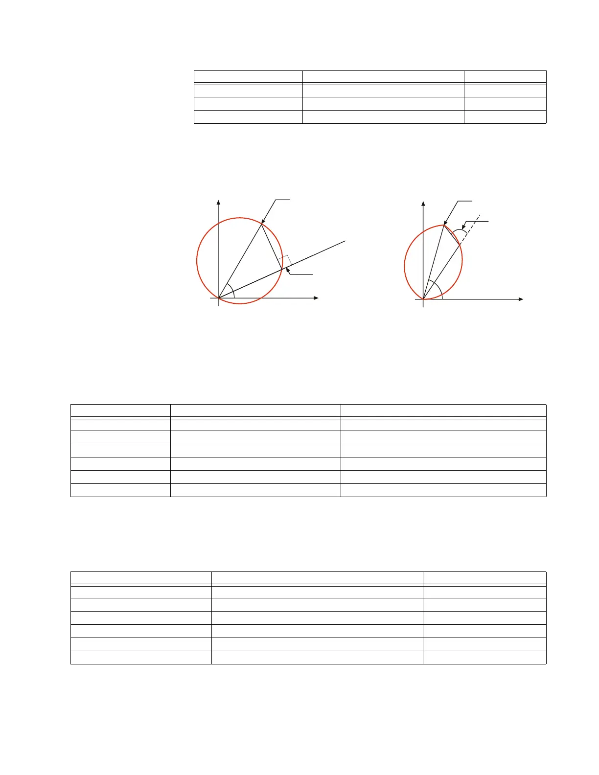
The limit angle of the comparator is adjustable. This allows the user to shape the
characteristic as a mho or a lens as shown in the following figure. The memory-polarized
mho characteristic has excellent built-in directional integrity. See the Memory Polarization
section later for details.
Figure 550: Mho and lens characteristics
Non-directional mho characteristic
The non-directional mho characteristic is achieved by checking the angle between the two
values for the various phase and ground distance elements shown in the table.
Table 15-1: Non-directional mho characteristic angle calculation parameters
Mho reactance characteristic for directional applications
The mho reactance characteristic is achieved by checking the angle between the two
values for the various phase and ground distance elements shown in the table.
Table 15-2: Mho reactance characteristic angle calculation parameters
A ground element I
A
× Z + I_0 × K
0
× Z + I
G
× K
0M
× Z – V
A
V
A
_1M
B ground element I
B
× Z + I_0 × K
0
× Z + I
G
× K
0M
× Z – V
B
V
B
_1M
C ground element I
C
× Z + I_0 × K
0
× Z + I
G
× K
0M
× Z – V
C
V
C
_1M
Element Value 1 Value 2
$&'5
5
5HDFKVHWWLQJ
;
&RPSDUDWRUDQJOH
VHWWLQJ
5
&RPSDUDWRUDQJOH
VHWWLQJ
5HDFKVHWWLQJ
;
0KRFKDUDFWHULVWLF /HQVFKDUDFWHULVWLF
Element Value 1 Value 2
AB phase element (I
A
– I
B
) × Z – (V
A
– V
B
)(V
A
– V
B
) – (I
A
– I
B
) × Z
REV
BC phase element (I
B
– I
C
) × Z – (V
B
– V
C
)(V
B
– V
C
) – (I
B
– I
C
) × Z
REV
CA phase element (I
C
– I
A
) × Z – (V
C
– V
A
)(V
C
– V
A
) – (I
C
– I
A
) × Z
REV
A ground element I
A
× Z + I_0 × K
0
× Z + I
G
× K
0M
× Z – V
A
V
A
– (I
A
× Z
REV
+ I_0 × K
0
× Z
REV
+ I
G
× K
0M
× Z
REV
)
B ground element I
B
× Z + I_0 × K
0
× Z + I
G
× K
0M
× Z – V
B
V
B
– (I
B
× Z
REV
+ I_0 × K
0
× Z
REV
+ I
G
× K
0M
× Z
REV
)
C ground element I
C
× Z + I_0 × K
0
× Z + I
G
× K
0M
× Z – V
C
V
C
– (I
C
× Z
REV
+ I_0 × K
0
× Z
REV
+ I
G
× K
0M
× Z
REV
)
Element Value 1 Value 2
AB phase element (I
A
– I
B
) × Z – (V
A
– V
B
)(I
A
– I
B
) × Z
BC phase element (I
B
– I
C
) × Z – (V
B
– V
C
)(I
B
– I
C
) × Z
CA phase element (I
C
– I
A
) × Z – (V
C
– V
A
)(I
C
– I
A
) × Z
A ground element I
A
× Z + I_0 × K
0
× Z + I
G
× K
0M
× Z – V
A
(I_0) × Z
B ground element I
B
× Z + I_0 × K
0
× Z + I
G
× K
0M
× Z – V
B
(I_0) × Z
C ground element I
C
× Z + I_0 × K
0
× Z + I
G
× K
0M
× Z – V
C
(I_0) × Z