632 D90
PLUS
LINE DISTANCE PROTECTION SYSTEM – INSTRUCTION MANUAL
DISTANCE ELEMENTS CHAPTER 15: THEORY OF OPERATION
If the mho characteristic is selected, the limit angle of the comparator is adjustable
concurrently with the limit angle of the mho characteristic, resulting in a tent shape
complementing the lens characteristic being effectively applied.
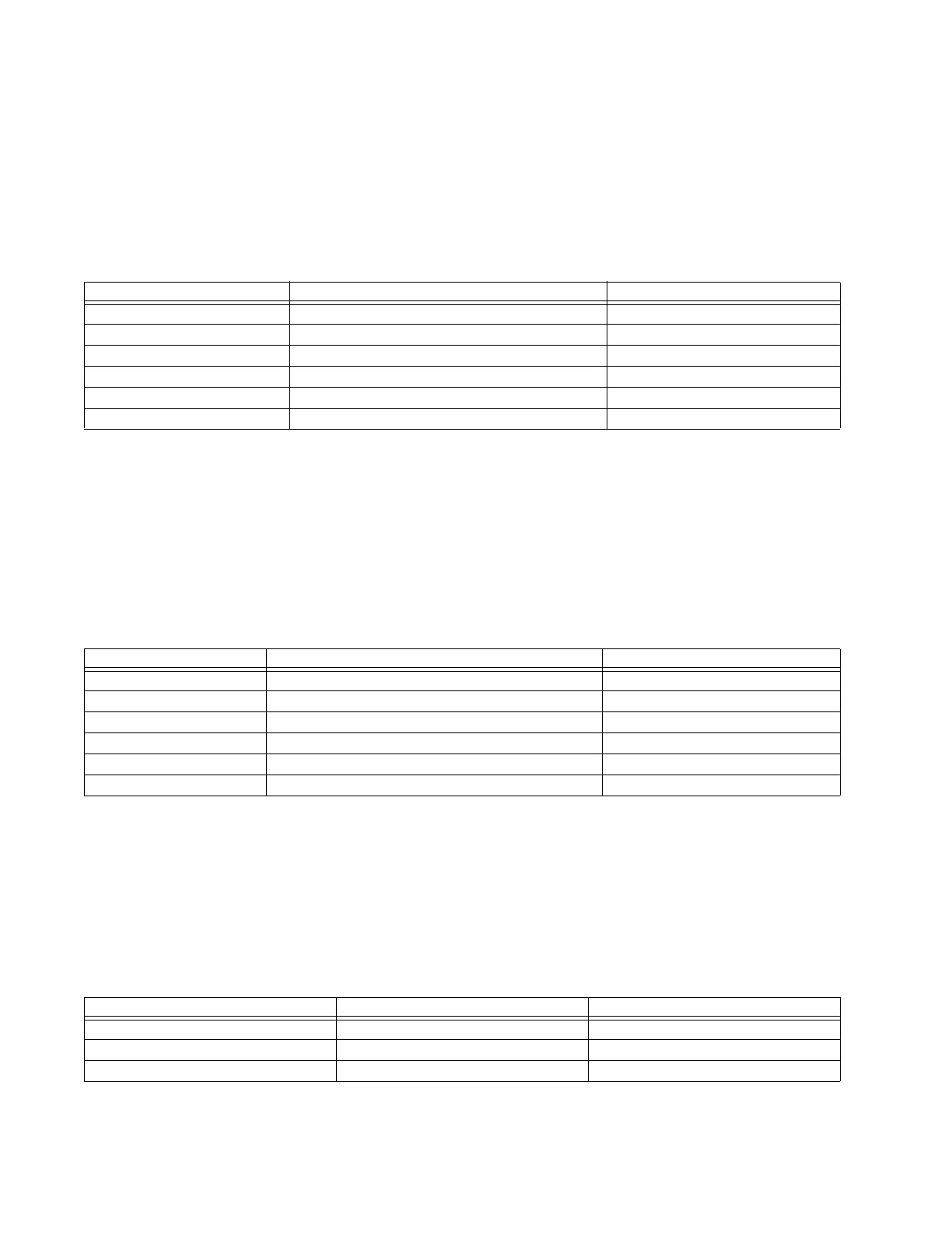
Quadrilateral reactance characteristic for directional applications
The quadrilateral reactance characteristic is achieved by checking the angle between the
two values for the various phase and ground distance elements shown in the table.
Table 15-3: Quadrilateral reactance characteristic angle calculation parameters
The ground elements are polarized from either zero-sequence or negative-sequence
current as per the programmed settings to maximize performance in non-homogeneous
systems. The polarizing current is shifted additionally by the user-programmable non-
homogeneity correction angle.
Reverse quadrilateral reactance characteristic for non-directional applications
The reverse quadrilateral reactance characteristic is achieved by checking the angle
between the two values for the various phase and ground distance elements shown in the
table.
Table 15-4: Reverse quadrilateral reactance characteristic angle calculation parameters
The ground elements are polarized from either zero-sequence or negative-sequence
current as per the programmed settings to maximize performance in non-homogeneous
systems. The polarizing current is shifted additionally by the user-programmable non-
homogeneity correction angle.
Directional characteristic
The directional characteristic is achieved by checking the angle between the two values
for the various phase and ground distance elements shown in the table.
Table 15-5: Directional characteristic angle calculation parameters
Element Value 1 Value 2
AB phase element (I
A
– I
B
) × Z – (V
A
– V
B
)(I
A
– I
B
) × Z
BC phase element (I
B
– I
C
) × Z – (V
B
– V
C
)(I
B
– I
C
) × Z
CA phase element (I
C
– I
A
) × Z – (V
C
– V
A
)(I
C
– I
A
) × Z
A ground element I
A
× Z + I_0 × K
0
× Z + I
G
× K
0M
× Z – V
A
(j × I_0 or j × I_2A) × e
jΘ
B ground element I
B
× Z + I_0 × K
0
× Z + I
G
× K
0M
× Z – V
B
(j × I_0 or j × I_2B) × e
jΘ
C ground element I
C
× Z + I_0 × K
0
× Z + I
G
× K
0M
× Z – V
C
(j × I_0 or j × I_2C) × e
jΘ
Element Value 1 Value 2
AB phase element (I
A
– I
B
) × Z
REV
– (V
A
– V
B
)(I
A
– I
B
) × Z
REV
BC phase element (I
B
– I
C
) × Z
REV
– (V
B
– V
C
)(I
B
– I
C
) × Z
REV
CA phase element (I
C
– I
A
) × Z
REV
– (V
C
– V
A
)(I
C
– I
A
) × Z
REV
A ground element I
A
× Z
REV
+ I_0 × K
0
× Z
REV
+ I
G
× K
0M
× Z
REV
– V
A
(j × I_0 or j × I_2A) × e
j(180° + Θ)
B ground element I
B
× Z
REV
+ I_0 × K
0
× Z
REV
+ I
G
× K
0M
× Z
REV
– V
B
(j × I_0 or j × I_2B) × e
j(180° + Θ)
C ground element I
C
× Z
REV
+ I_0 × K
0
× Z
REV
+ I
G
× K
0M
× Z
REV
– V
C
(j × I_0 or j × I_2C) × e
j(180° + Θ)
Element Value 1 Value 2
AB phase element (I
A
– I
B
) × Z
D
(V
A
– V
B
)_1M
BC phase element (I
B
– I
C
) × Z
D
(V
B
– V
C
)_1M
CA phase element (I
C
– I
A
) × Z
D
(V
C
– V
A
)_1M