CHAPTER 15: THEORY OF OPERATION DISTANCE ELEMENTS
D90
PLUS
LINE DISTANCE PROTECTION SYSTEM – INSTRUCTION MANUAL 633
The characteristic and limit angles of the directional comparator are adjusted
independently from the mho and reactance comparators. The directional characteristic
improves the directional integrity of the distance functions.
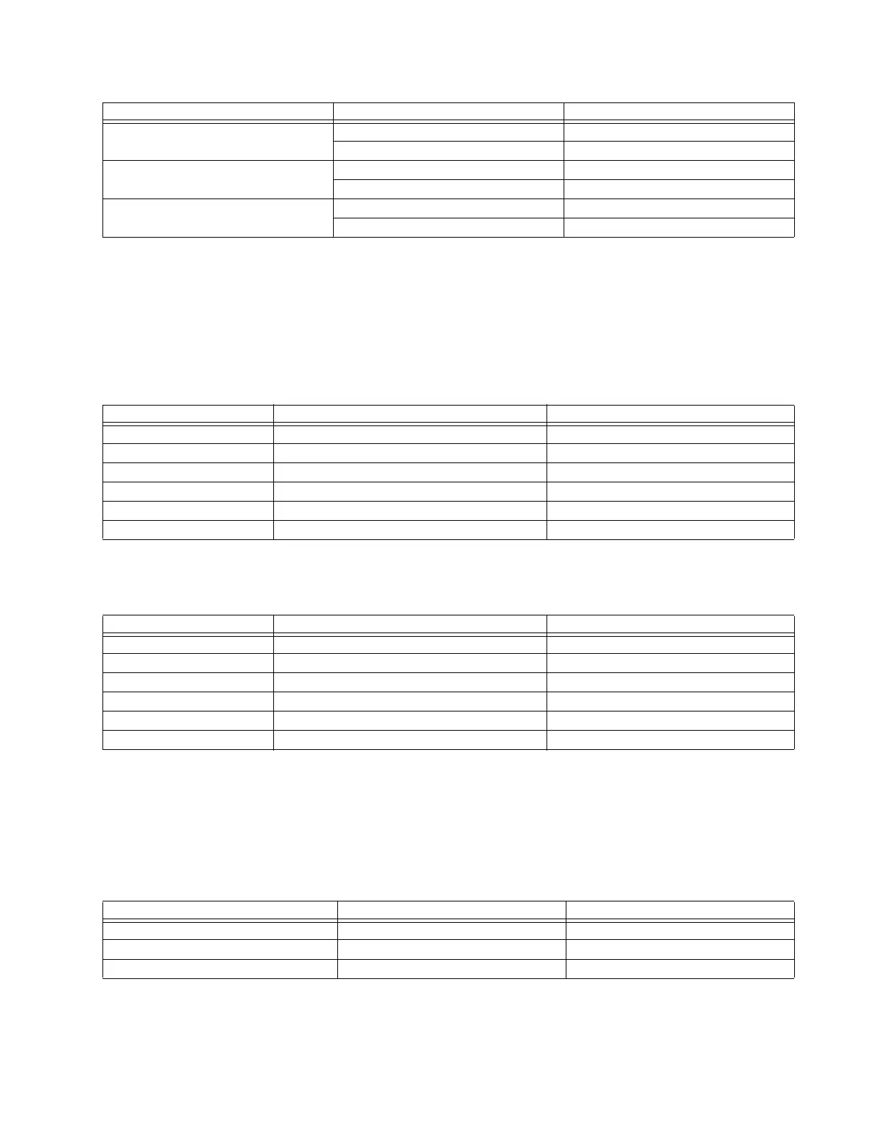
Right and left blinder characteristics
The right blinder characteristic is achieved by checking the angle between the two values
for the various phase and ground distance elements shown in the table.
Table 15-6: Right blinder characteristic angle calculation parameters
Similarly, the left right blinder characteristic is achieved by checking the angle between the
two values for the various phase and ground distance elements shown in the table.
Table 15-7: Left blinder characteristic angle calculation parameters
The blinders apply to the quadrilateral characteristic only.
Fault type characteristic
The fault type characteristic is achieved by checking the angle between the two values for
the elements shown in the table. This characteristic applies to ground distance elements
only.
Table 15-8: Fault type characteristic angle calculation parameters
A ground element I_0 × Z
D
V
A
_1M
I
A
_2 × Z
D
V
A
_1M
B ground element I_0 × Z
D
V
B
_1M
I
B
_2 × Z
D
V
B
_1M
C ground element I_0 × Z
D
V
C
_1M
I
C
_2 × Z
D
V
C
_1M
Element Value 1 Value 2
Element Value 1 Value 2
AB phase element (I
A
– I
B
) × Z
R
– (V
A
– V
B
)(I
A
– I
B
) × Z
R
BC phase element (I
B
– I
C
) × Z
R
– (V
B
– V
C
)(I
B
– I
C
) × Z
R
CA phase element (I
C
– I
A
) × Z
R
– (V
C
– V
A
)(I
C
– I
A
) × Z
R
A ground element I
A
× Z
R
+ I_0 × K
0
× Z
R
+ I
G
× K
0M
× Z
R
– V
A
I
A
× Z
R
+ I_0 × K
0
× Z
R
+ I
G
× K
0M
× Z
R
B ground element I
B
× Z
R
+ I_0 × K
0
× Z
R
+ I
G
× K
0M
× Z
R
– V
B
I
B
× Z
R
+ I_0 × K
0
× Z
R
+ I
G
× K
0M
× Z
R
C ground element I
C
× Z
R
+ I_0 × K
0
× Z
R
+ I
G
× K
0M
× Z
R
– V
C
I
C
× Z
R
+ I_0 × K
0
× Z
R
+ I
G
× K
0M
× Z
R
Element Value 1 Value 2
AB phase element (I
A
– I
B
) × Z
L
– (V
A
– V
B
)(I
A
– I
B
) × Z
L
BC phase element (I
B
– I
C
) × Z
L
– (V
B
– V
C
)(I
B
– I
C
) × Z
L
CA phase element (I
C
– I
A
) × Z
L
– (V
C
– V
A
)(I
C
– I
A
) × Z
L
A ground element I
A
× Z
L
+ I_0 × K
0
× Z
L
+ I
G
× K
0M
× Z
L
– V
A
I
A
× Z
L
+ I_0 × K
0
× Z
L
+ I
G
× K
0M
× Z
L
B ground element I
B
× Z
L
+ I_0 × K
0
× Z
L
+ I
G
× K
0M
× Z
L
– V
B
I
B
× Z
L
+ I_0 × K
0
× Z
L
+ I
G
× K
0M
× Z
L
C ground element I
C
× Z
R
+ I_0 × K
0
× Z
L
+ I
G
× K
0M
× Z
L
– V
C
I
C
× Z
R
+ I_0 × K
0
× Z
L
+ I
G
× K
0M
× Z
L
Element Value 1 Value 2
A ground element I_0 I
A
_2
B ground element I_0 I
B
_2
C ground element I_0 I
C
_2