GE HEALTHCARE
DIRECTION 5394152, Revision 5
LOGIQ™ P6/P6 PRO SERVICE MANUAL
Page 8-22 Section 8-2 - DISASSEMBLY/RE-ASSEMBLY
8-2-4-4 Assembly procedure (cont’d)
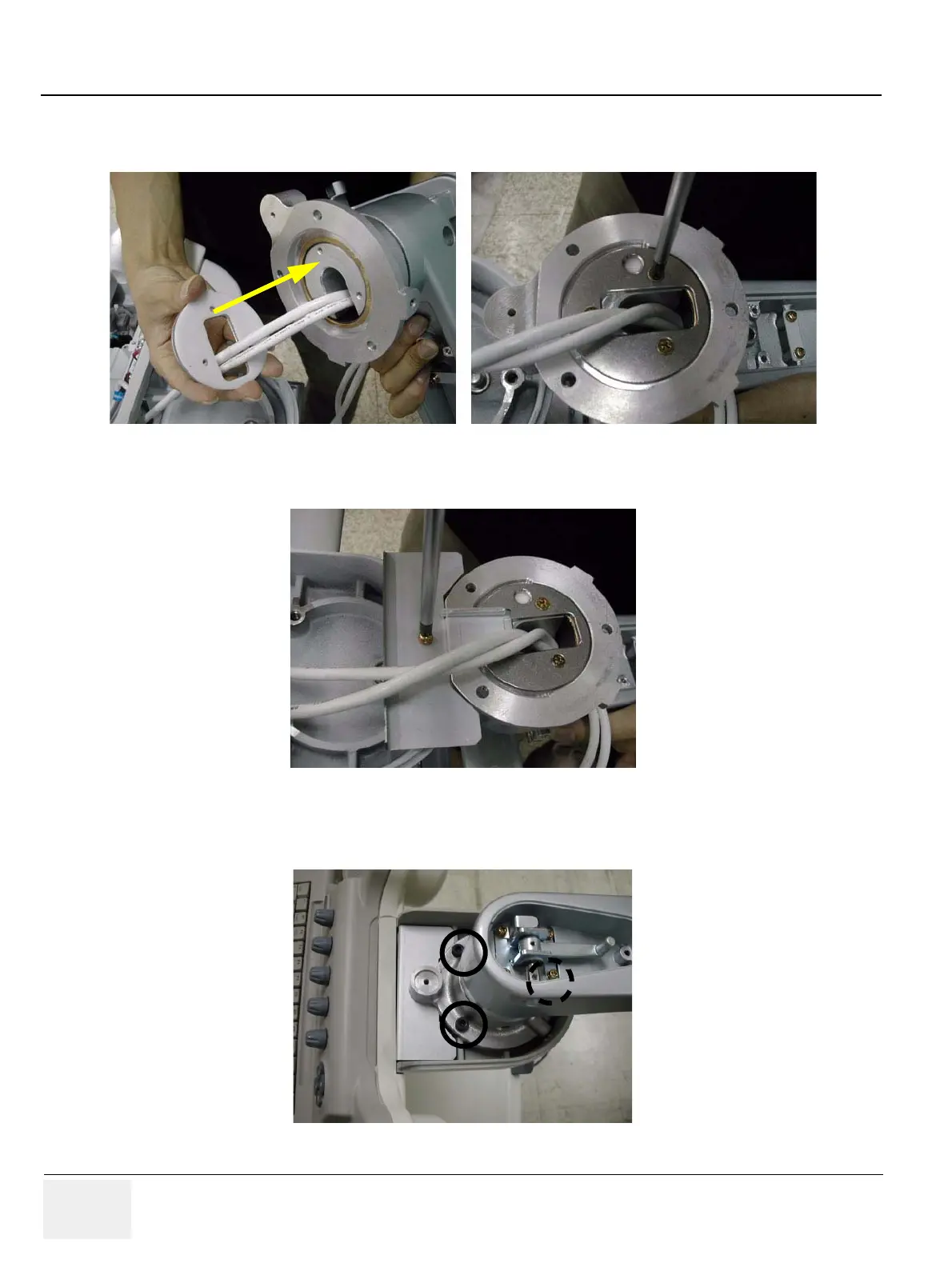
4.) Screw 3 screws (2373562, FH M4X10 YEL) to fix the flexible arm stopper after adjusting the holes.
5.) Screw 1 screw (2159625, PH M4X8 W/SP) to install OP bracket.
6.) Screw 3 screws (5327646, HSH M6X16 WHT) to install the arm neck pipe. Make sure place DVI
cable be on the right side, power cable on the left side.
Figure 8-39 Fixing the flexible arm stopper
Figure 8-40 Installing OP Bracket
Figure 8-41 Assembling the arm neck pipe

 Loading...


