GE HEALTHCARE
DIRECTION 5394152, Revision 5
LOGIQ™ P6/P6 PRO SERVICE MANUAL
Chapter 8 - Page 8-23
8-2-4-4 Assembly procedure (cont’d)
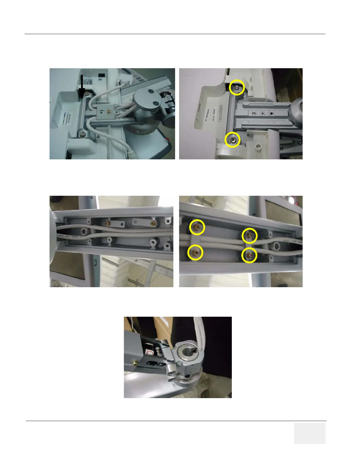
7.) Screw 2 screws (5177684, HSH M5X20 WHT) to assemble the LCD monitor with flexible arm Top
part.
8.) Insert the two cables inside the Flexible arm and Screw 4 screws (2159625, PH M4X8 W/SP) to
assemble the Lower arm cable bracket.
9.) Put in the two cables. Make sure place DVI cable be on the right side, power cable on the left side.
Figure 8-42 Screwing 2 screws
Figure 8-43 Screwing 4 screws
Figure 8-44 Putting in the cables

 Loading...


