EasyManuals Logo

GE LOGIQ P6 Series User Manual

GE LOGIQ P6 Series
484 pages
To Next Page IconTo Next Page
To Previous Page IconTo Previous Page
Page #251 background imageLoading...
Page #251 background image
GE HEALTHCARE
DIRECTION 5394152, Revision 5
LOGIQ™ P6/P6 PRO SERVICE MANUAL
Chapter 8 - Page 8-25
8-2-4-4 Assembly procedure (cont’d)
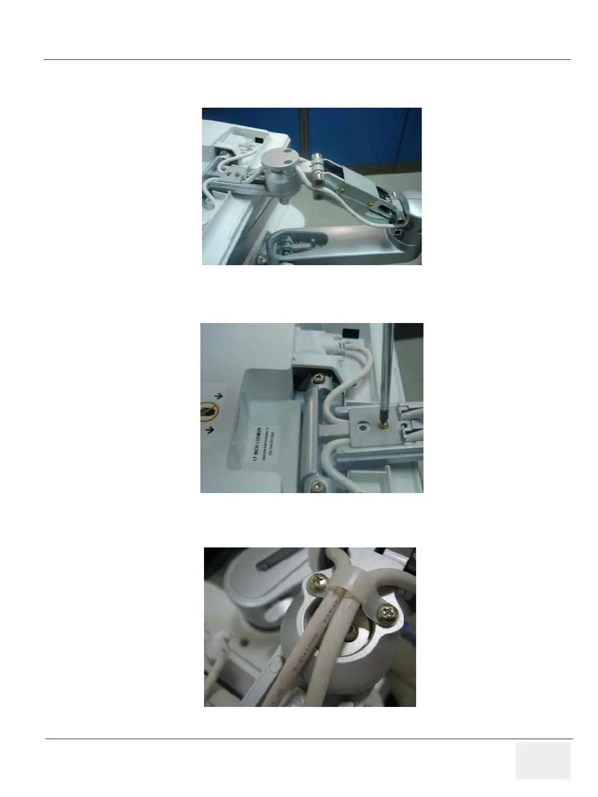
13.)Place the cables inside the slot and connect power cable and DVI cable.
14.)Assemble the Cable bracket with 1 Screw (2159625, PH M4X8 W/SP)
15.)Screw 2 screws (2159634, BH M4X10 WHT) to assemble the Cable clamp.
Figure 8-48 Placing the Cables
Figure 8-49 Assembling the Cable bracket
Figure 8-50 Assembling the Cable clamp

Table of Contents

Questions and Answers:

Question and Answer IconNeed help?

Do you have a question about the GE LOGIQ P6 Series and is the answer not in the manual?

GE LOGIQ P6 Series Specifications

General IconGeneral
Power Supply100-240 VAC, 50/60 Hz
Imaging ModesB-Mode, M-Mode, Color Doppler, Power Doppler
ApplicationsVascular, Musculoskeletal
Operating Temperature10°C to 40°C
Display15-inch LCD
Relative Humidity20% to 80% (non-condensing)

Related product manuals