The DDB signal Thermal T
rip indicates tripping of the element . A further DDB signal Thermal Alarm is generated
from the thermal alarm stage. The state of the DDB signal can be programmed to be viewed in the Monitor Bit x
cells of the COMMISSION TESTS column in the relay.
E00776
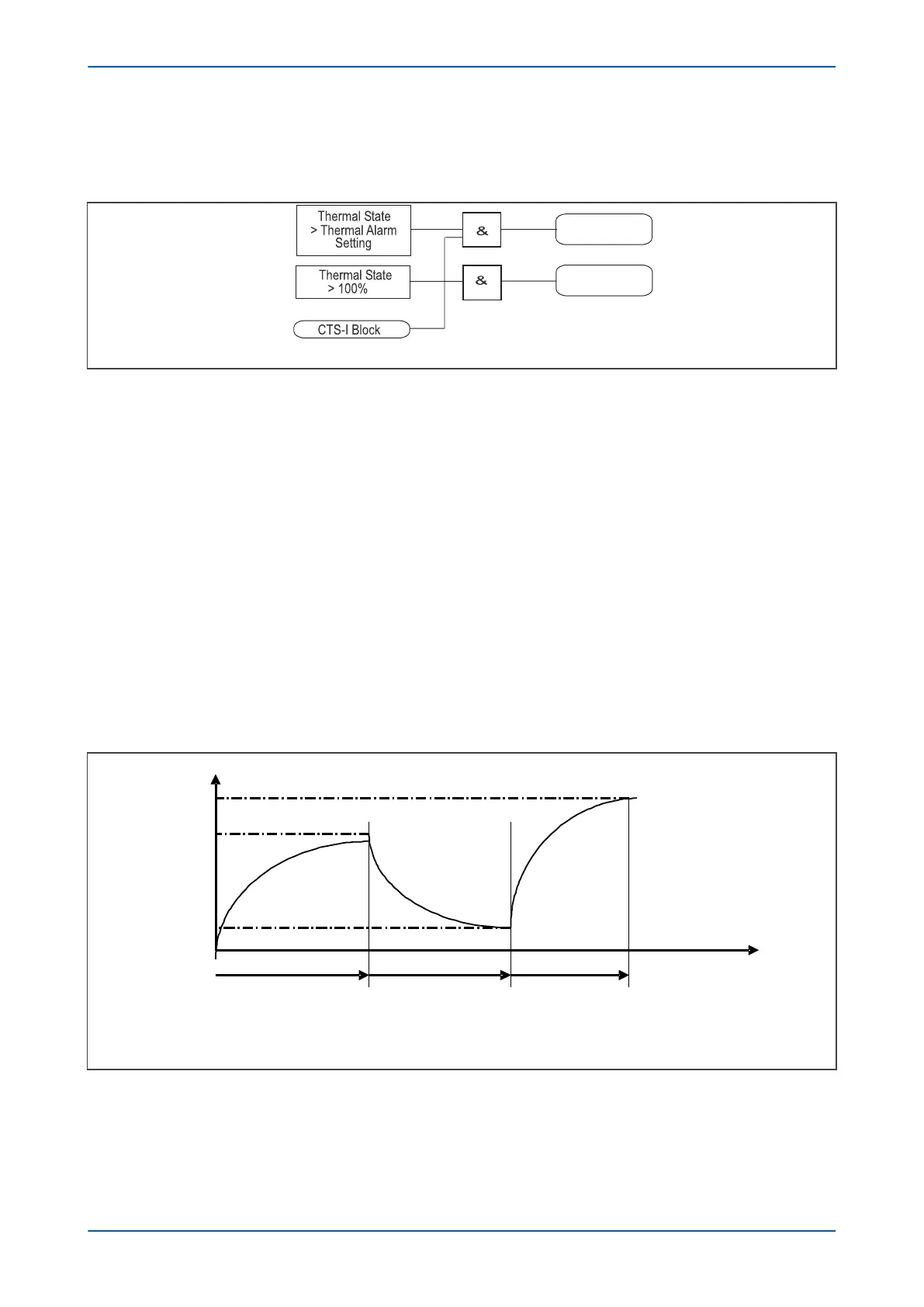
Gen
Thermal Alarm
Gen
Thermal Trip
P1629ENd
Figure 17: Thermal overload protection logic diagram
Thermal lock
out
This function compares the thermal capacity available with the lockout setting immediately after a trip, for
example when the interrupting device is open. If the thermal capacity available is insufficient to allow restart, an
output contact programmed for the lockout function (Thermal Lockout) is energized, which inhibits a restart.
When the motor has cooled down, this function resets the lockout output contact.
The thermal lockout drops off at 97% of the thermal lockout threshold.
The estimated time to next start is the time to reach the thermal lockout threshold. This is in the MEASUREMENTS 3
menu and is given by the following formula:
T = T
r
* Ln (q
1
/q
2
)
Where:
T
r
= cooling time constant,
q
1
= initial thermal state,
q
2
= final thermal state = 97% of thermal lockout threshold.
Thermal State
Time
T1 T2 T3
20 %
80 %
100 %
P0658ENa
Figure 18: Cooling time constant
P24xM Chapter 6 - Current Protection Functions
P24xM-TM-EN-2.1 77