4.2 NON-DIRECTIONAL OVERCURRENT LOGIC
I>1 Timer Block
I>1 Start A
I>1 Trip A
I>1 Start
I>1 Trip
IA2H Sta rt
I> Blocking
V04000
2H Blocks I>1
2H 1PH Block
I>1 Current Set
&
&
&
IDMT/DT
I>1 Start B
I>1 Trip B
IB2H Sta rt
I> Blocking
2H Blocks I>1
2H 1PH Block
I>1 Current Set
&
&
&
IDMT/DT
I>1 Start C
I>1 Trip C
I> Blocking
2H Blocks I>1
2H 1PH Block
I>1 Current Set
&
&
&
IDMT/DT
1
1
I2H Any Start
I> Blocking
2H Blocks I>1
2H 1PH Block
&
Timer Settings
Timer Settings
Timer Settings
IA
IB
IC
Notes: This diagram does not show all stages. Other stages follow
similar principles.
IC2H Start
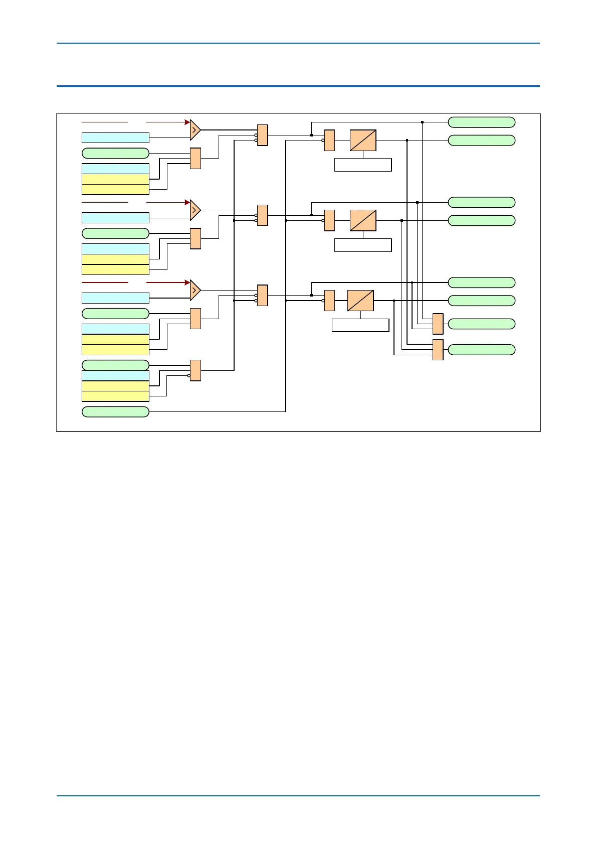
Figure 26: Non-directional Overcurrent Logic diagram
Phase O
vercurrent Modules are level detectors that detect when the current magnitude exceeds a set threshold.
When this happens, a Start signal is generated unless it is inhibited by a blocking signal. This Start signal initiates
the timer module, which can be configured as an IDMT timer or DT timer, depending on the stage number. The
Start signal is also available for use in the PSL. For each stage, there are three Phase Overcurrent Modules, one for
each phase. The three Start signals from each of these phases are combined to form a 3-phase Start signal.
The Start signals can be blocked by the Second Harmonic blocking function; on a per phase basis (single-phase
blocking) or for all three phases at once (three-phase blocking). The relevant bits are set in the I> Blocking cell and
this is combined with the relevant second harmonic blocking DDBs.
The timer can be configured with several settings depening on which type of timer is selected. Taking stage 1 as
an example:
The setting I>1 Time Delay sets the DT time delay
The setting I>1 TMS sets the Time Multiplier setting for IEC IDMT curves
The setting I>1 Time Dial sets the Time Multiplier setting for IEEE/US IDMT curves
The setting I>1 DT Adder adds a fixed time delay to the IDMT operate characteristic
The setting I>1 tRESET determines the reset time for the DT characteristic
The outputs of the timer modules are the single-phase trip signals. These trip signals are combined to form a 3-
phase Trip signal.
The timer modules can be blocked by a Phase Overcurrent Timer Block (for example I>1 Timer Block).
For DT-only stages, the DT timer can be blocked by the Autoreclose function. An Autoreclose blocking signal is
produced by the DDB signal AR Blk Main Prot and the relevant settings in the I> Blocking cell.
P24xM Chapter 6 - Current Protection Functions
P24xM-TM-EN-2.1 95