The unbalance current detected by a core balance current transformer on the healthy feeders can be seen to be a
simple v
ector addition of Ia1 and Ib1, giving a residual current which lies at exactly 90° lagging the residual
voltage. As the healthy phase voltages have risen by a factor of Ö3, the charging currents on these phases are also
·3 times larger than their steady state values. Therefore, the magnitude of residual current, IR1, is equal to 3 x the
steady state per phase charging current.
Note:
The actual residual voltage used as a reference signal for directional earth fault relays is phase shifted by 180° and is
therefore shown as -3 Vo in the vector diagrams. This phase shift is automatically introduced within the P24xM relays.
On the faulted feeder, the residual current is the addition of the charging current on the healthy phases (Ih3) plus
the fault curr
ent (If). The net unbalance is therefore equal to Il-Ih1-Ih2.
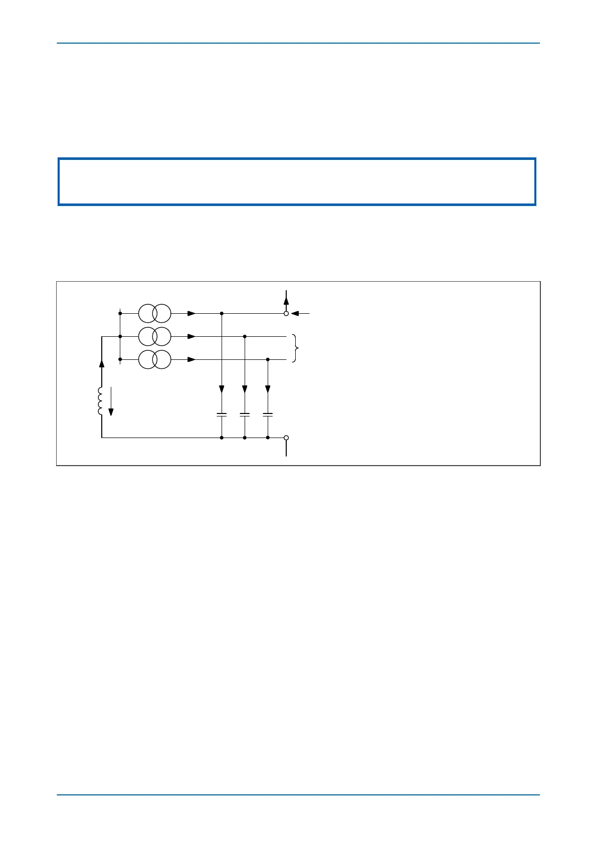
This situation is more readily observed by considering the zero sequence network for this fault condition. This is
shown in figure below.
V00640
I
ROF
= Residual current on faulted feeder
I
ROH
= Residual current on healthy feeder
IOF = IL – IH1 – IH2 – IH3
I
ROF
= I
H3
+ I
OF
so:
I
ROF
= I
L
– I
H1
– I
H2
3X
L
I
L
-V
0
X
CO
IH3 IH2 IH1
Healthy feeders
Faulty feeder
I
ROF
I
ROH
I
ROH
I
OF
Figure 54: Zero sequence network showing residual currents
When comparing the r
esidual currents occurring on the healthy and the faulted feeders the figure below shows
that the currents would be similar in both magnitude and phase. Therefore, it is not possible to apply a relay which
could provide discrimination.
However, the scenario of no resistance being present in the coil or feeder cables is purely theoretical. Further
consideration needs to be given to a practical application in which the resistive component is no longer ignored.
P24xM Chapter 6 - Current Protection Functions
P24xM-TM-EN-2.1 127