E00800
IED
S F
V
RES
=
Z
S0
2Z
S1
+ Z
S0
+ 2Z
L1
+ Z
L0
X 3 E
E
Z
S
Z
L
V
A
V
A
V
A
V
A
V
C
V
C
V
C
V
C
V
C
V
C
V
B
V
B
V
B
V
B
V
B
V
B
V
RES
V
RES
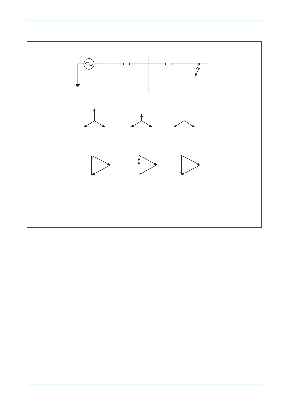
Figure 101: Residual voltage for a solidly earthed system
As can be seen fr
om the above diagram, the residual voltage measured on a solidly earthed system is solely
dependent on the ratio of source impedance behind the protection to the line impedance in front of the protection,
up to the point of fault. For a remote fault far away, the Z
S
/Z
L
: ratio will be small, resulting in a correspondingly
small residual voltage. Therefore, the protection only operates for faults up to a certain distance along the system.
The maximum distance depends on the device setting.
4.3.2 CALCULATION FOR IMPEDANCE EARTHED SYSTEMS
Consider a Phase-A to Earth fault on a simple radial system.
Chapter 10 - Voltage Protection Functions P24xM
212 P24xM-TM-EN-2.1