Directionality is achieved by using differet techniques depending on the application. The directional SEF can be
used for
:
● Solidly earthed systems
● Unearthed systems (insulated systems)
● Compensated systems
● Resistance earthed systems
The device supports standard core-balanced directional control as well as Isin(f), Icos(f) and Wattmetric
characteristics.
If you are using directional SEF protection, you select the required polarisation using the SEF Options setting in the
SEF PROTECTION column.
8.4.1 WATTMETRIC CHARACTERISTIC
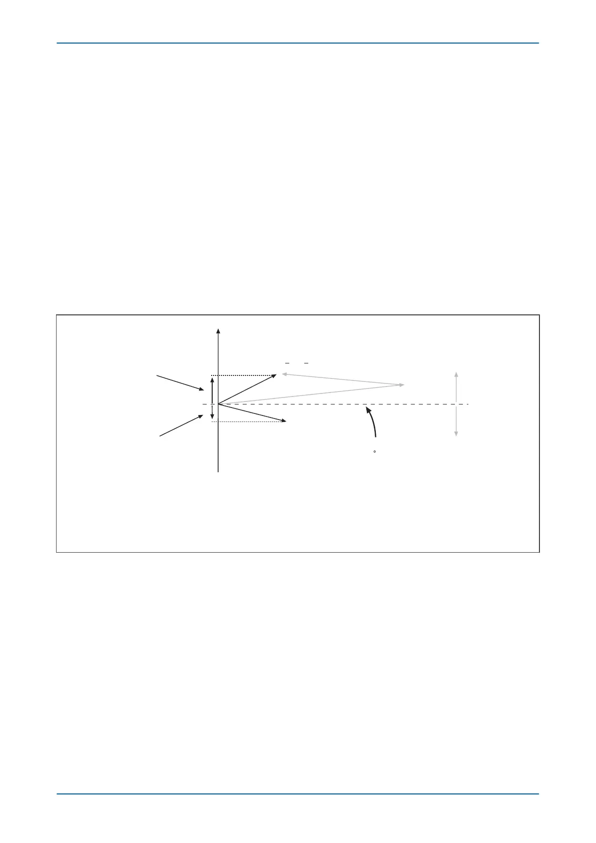
Analysis has shown that a small angular difference exists between the spill current on healthy and faulted feeders
for ear
th faults on compensated networks. This angular difference gives rise to active components of current
which are in anti-phase to one another.
E00617
Active component
of residual current:
Faulted Feeder
Active component
of residual current:
Healthy Feeder
V
res = -3Vo
Operate
Restrain
Zero torque line
for 0 RCA
Key:
- Residual current on faulty feeder
- Residual current on healthy feeder
- Charging current from rest of system
- Current through earthed coil
IR1
IR1
IR3
IR3
IH1, IH2
IH2
IH1
IL
IL
Figure 58: Resistive components of spill current
Consequently, the activ
e components of zero sequence power will also lie in similar planes, meaning an IED
capable of detecting active power can make discriminatory decisions. If the Wattmetric component of zero
sequence power is detected in the forward direction, then this would indicate fault on that feeder. If power is
detected in the reverse direction, then the fault must be present on an adjacent feeder or at the source.
For operation of the directional earth fault element, all three of the settable thresholds must be exceeded; namely
the current ISEF>, the voltage ISEF>VNpol Set and the power PN> Setting.
The power setting is called PN> and is calculated using residual quantities. The formula for operation is as follows:
The PN> setting corresponds to:
V
res
I
res
cos(
f f
c
) = 9V
o
I
o
cos(
f f
c
)
Chapter 6 - Current Protection Functions P24xM
132 P24xM-TM-EN-2.1