8 SENSITIVE EARTH FAULT PROTECTION
With some earth faults, the fault current flowing to earth is limited by either intentional resistance (as is the case
with some HV systems) or unintentional r
esistance (e.g. in very dry conditions and where the substrate is high
resistance, such as sand or rock).
To provide protection in such cases, it is necessary to provide an earth fault protection system with a setting that is
considerably lower than for normal line protection. Such sensitivity cannot be provided with conventional CTs,
therefore the SEF input would normally be fed from a core balance current transformer (CBCT) mounted around
the three phases of the feeder cable. The SEF transformer should be a special measurement class transformer.
8.1 SEF PROTECTION IMPLEMENTATION
The product provides four stages of SEF protection with independent time delay characteristics.
S
tages 1, 2 provide a choice of operate and reset characteristics, where you can select between:
● A range of IDMT (Inverse Definite Minimum Time) curves
● A range of User-defined curves
● DT (Definite Time)
This is achieved using the cells
● ISEF>(n) Function for the overcurrent operate characteristic
● ISEF>(n) Reset Char for the overcurrent reset characteristic
● ISEF>(n) Usr RstChar for the reset characteristic for user -defined curves
where (n) is the number of the stage.
Stages 1 and 2 also provide a Timer Hold facility. This is configured using the cells ISEF>(n) tReset.
Stages 3 and 4 have definite time characteristics only.
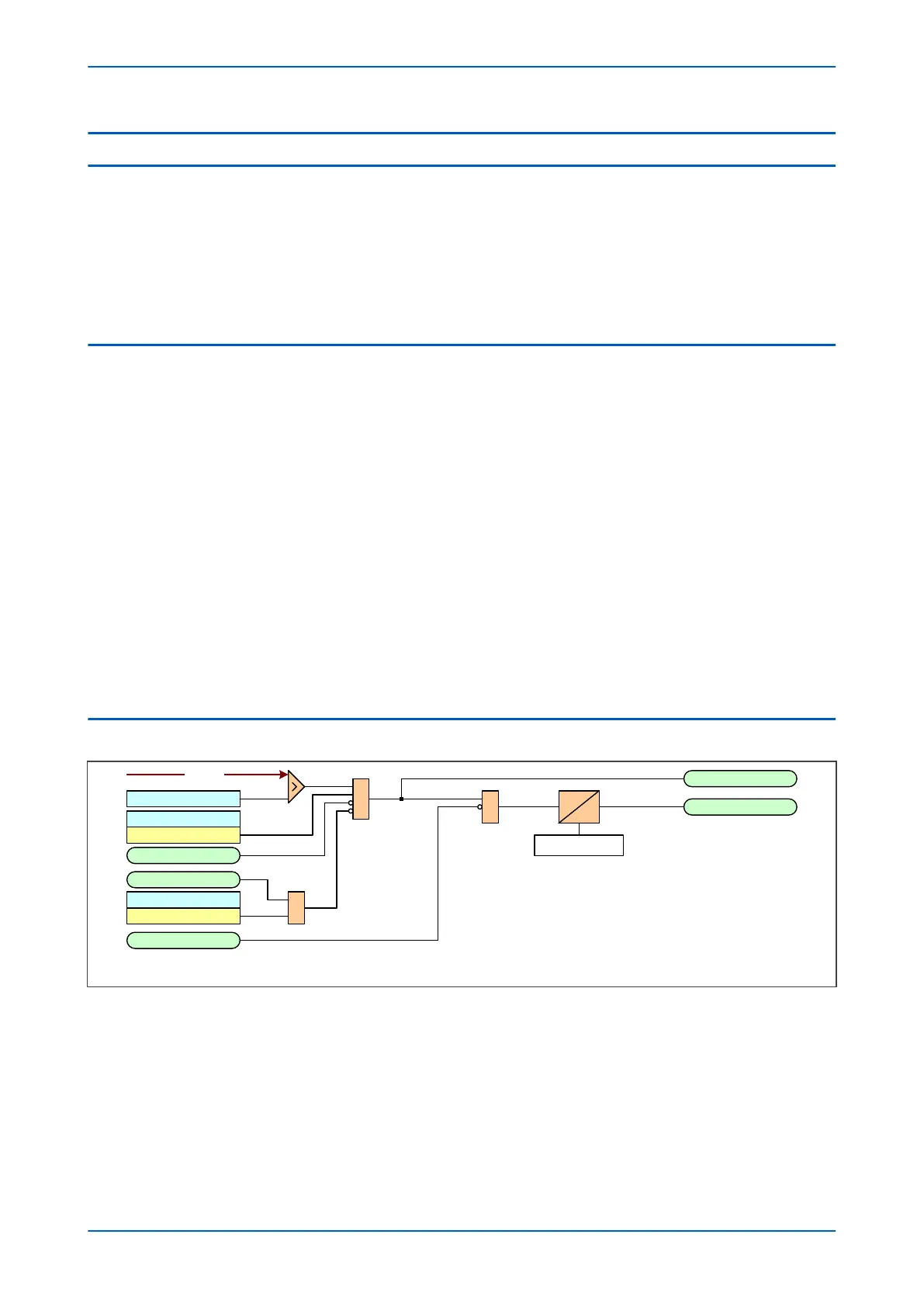
8.2 NON-DIRECTIONAL SEF LOGIC
ISEF>1 Timer Blk
ISEF>1 Start
ISEF>1 Trip
I2H Any Start
ISEF> Blocking
V04004
2H Blocks ISEF>1
Inhibit SEF
ISEF>1 Current
ISEF>1 Direction
Non-directional
&
IDMT/DT
Timer Settings
&
&
ISEF
Note: This diagram does not show all stages. Other stages follow similar
princip les.
Note: This diagram does not show all stages. Other stages follow similar
princip les.
Figure 56: Non-directional SEF logic
The SEF curr
ent is compared with a set threshold (ISEF>(n) Current) for each stage. If it exceeds this threshold, a
Start signal is triggered, providing it is not blocked. This can be blocked by the second harmonic blocking function,
or an Inhibit SEF DDB signal.
The autoreclose logic can be set to block the SEF trip after a prescribed number of shots (set in AUTORECLOSE
column). This is achieved using the AR Blk Main Prot setting. This can also be blocked by the relevant timer block
signal ISEF>(n)TimerBlk DDB signal.
Chapter 6 - Current Protection Functions P24xM
130 P24xM-TM-EN-2.1