V01202
All Poles Dead
VTS I> Inhibit
VTS I> Inhibit
VTS I> Inhibit
1
VTS PickupThresh
VTS PickupThresh
VTS PickupThresh
Hardcoded threshold
I2>1 Current Set
Hardcoded threshold
Hardcoded threshold
Hardcoded threshold
Any Pole Dead
VTS Reset Mode
Manual
Auto
MCB/VTS
VTS Status
Indication
Blocking
VTS Acc Ind
&
&
1
&
&
&1
S
R
Q
1
&
S
R
Q
1
&
VTS Slow Block
VTS Fast Block
VT Fail Alarm
&1
&
&
1
S
R
Q
1
IA
IB
IC
VA
VB
VC
Delta IA
Delta IB
Delta IC
V2
I2
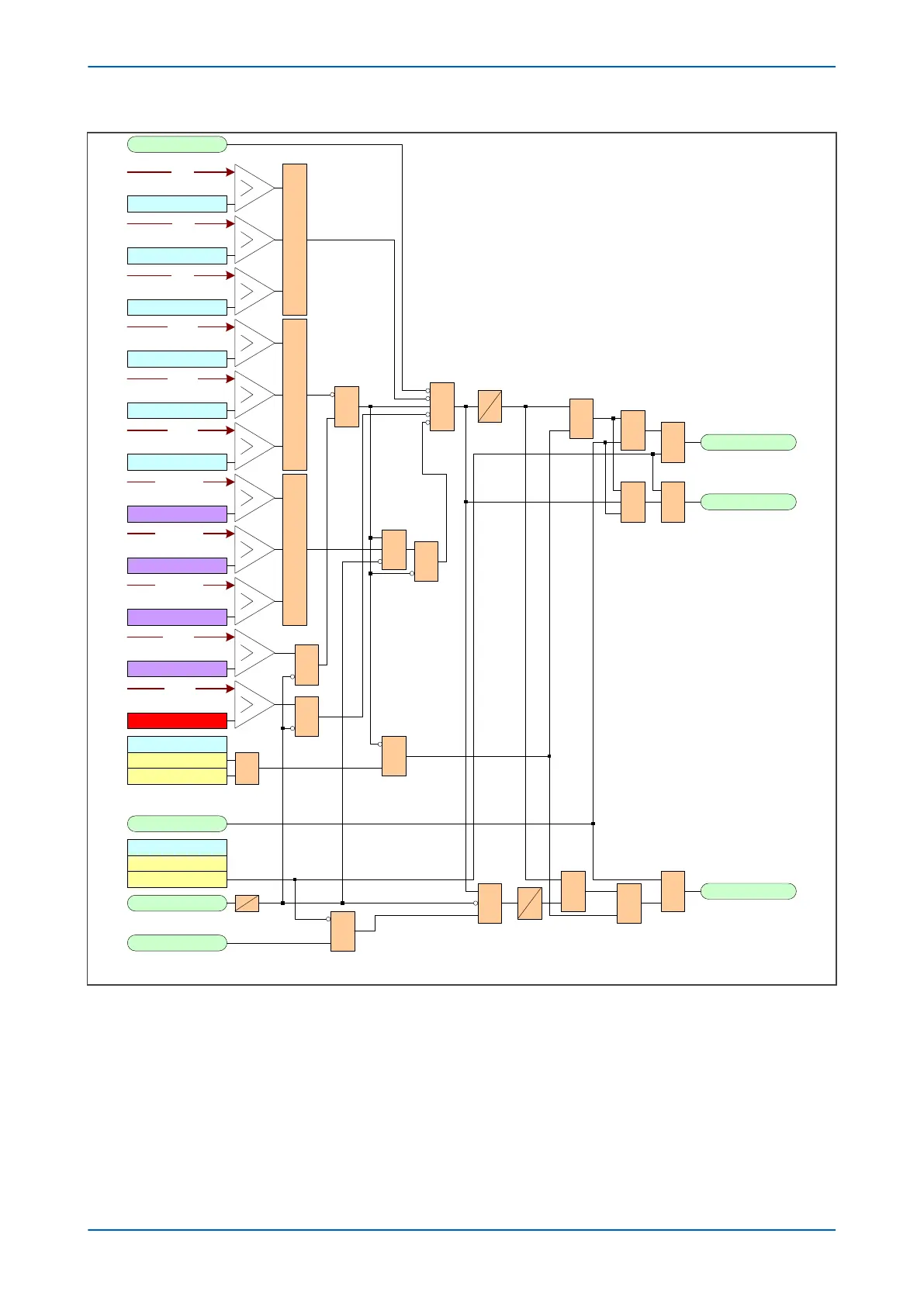
Figure 132: VTS logic
As can be seen fr
om the diagram, the VTS function is inhibited if:
● An All Poles Dead DDB signal is present
● Any phase overcurrent condition exists
● A Negative Phase Sequence current exists
● If the phase current changes over the period of 1 cycle
Chapter 14 - Supervision P24xM
278 P24xM-TM-EN-2.1