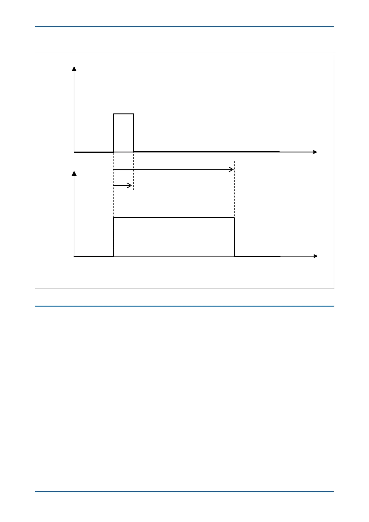
EasyManuals Logo

GE P24DM User Manual

GE P24DM
802 pages
To Next Page IconTo Next Page
To Previous Page IconTo Previous Page
Page #185 background imageLoading...
Page #185 background image
4. If the fault is cleared before the voltage memory signal expires, the memory algorithm resets and restarts
the two/four cycle validation process.
5. If there is no voltage memory available (either because the line has just been energised, or because the
memory voltage has expired), cross polarization is used instead. The contribution of cross polarizing signals
is only used when memory polarizing is invalid and is only valid for certain pole dead conditions.
6. If neither memory polarization voltage nor cross-polarization voltage is available (pole dead condition for
phase-to-phase element), then the phase-to-phase elements are self polarized. If the polarizing voltage is
less than 1V, only zone 1 is allowed to operate. In this case a Mho characteristic with a reverse offset of 25%
is applied. This ensures operation when closing on to a close-up three-phase fault (SOTF/ TOR condition).
One of the additional benefits of adding memory into the polarizing mix is that Mho characteristics offer dynamic
expansion if there is a forward fault, therefore covering greater fault arc resistance
3.2
QUADRILATERAL CHARACTERISTIC
A number of zones are provided to make up the Quadrilateral characteristics. The following diagram shows
examples of Directional Forward, Directional Reverse, and Offset zones:
Z1
Z2
ZQ (reverse)
ZP (forward)
Z3 (offset)
Z4
Reverse
Forward
Line Angle
+jX
+R
-R
E02785
Figure 60: Simplified quadrilateral characteristics
Programmable zones (zone P and Q) are also available. Similar to Zone 3, the programmable zones can be
configured as Offset, Directional Forward, or Directional Reverse.
A combination of simple comparators, each using signals derived from measured currents and voltages,
determines whether measured impedance is within a tripping zone. A separate comparator is used for each line of
each Quadrilateral.
Each tripping zone is constructed from a Quadrilateral based on that depicted in the following diagram:
P543i/P545i Chapter 7 - Distance Protection
P54x1i-TM-EN-1 149

Table of Contents

Questions and Answers:

Question and Answer IconNeed help?

Do you have a question about the GE P24DM and is the answer not in the manual?

GE P24DM Specifications

General IconGeneral
BrandGE
ModelP24DM
CategoryControl Unit
LanguageEnglish

Related product manuals