4.2 RESIDUAL OVERVOLTAGE LOGIC
VN>1 Voltage Set
VN>1 Trip
V00802
VN>1 Start
VN>1 Timer Blk
VTS Fast Block
&
&
IDMT/DT
VN
832
418
804
700
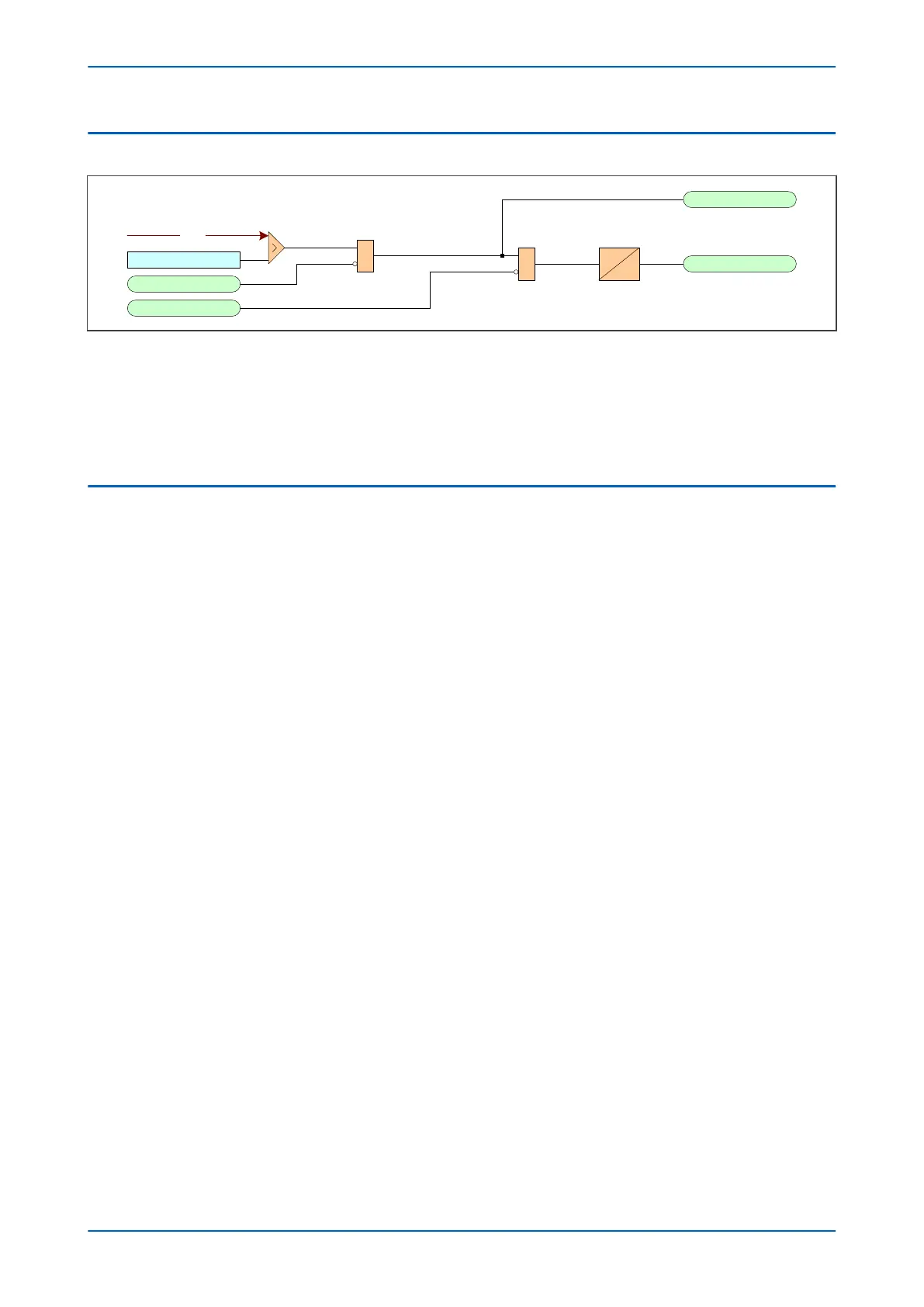
Figure 100: Residual Overvoltage logic
The R
esidual Overvoltage module (VN>) is a level detector that detects when the voltage magnitude exceeds a set
threshold, for each stage. When this happens, the comparator output produces a Start signal (VN>(n) Start), which
signifies the "Start of protection". This can be blocked by a VTS Fast block signal. This Start signal is applied to the
timer module. The output of the timer module is the VN> (n) Trip signal which is used to drive the tripping output
relay.
4.3 APPLICATION NOTES
4.3.1 CALCULATION FOR SOLIDLY EARTHED SYSTEMS
Consider a Phase-A to Earth fault on a simple radial system.
P24xM Chapter 10 - Voltage Protection Functions
P24xM-TM-EN-2.1 211