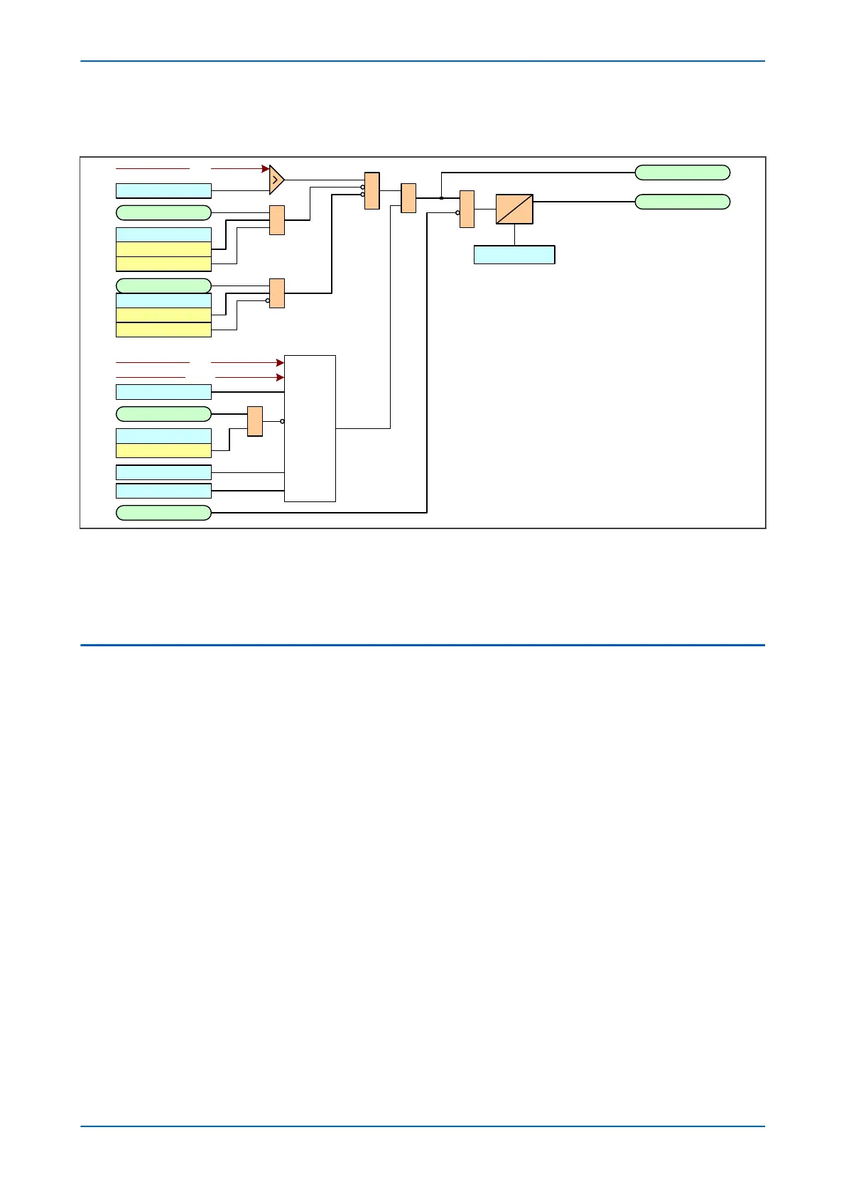
4.3.1 DIRECTIONAL OVERCURRENT LOGIC
I>1 Timer Block
V04001
VTS Fast Block
I> Blocking
VTS Blocks I>1
Directional
check
I>1 Direction
I>1 Start A
I>1 Trip A
IA2H Sta rt
I> Blocking
2H Block I>1
2H 1PH BLOCK
I>1 Current Set
&
IDMT/DT
Timer Settings
I2H Any Start
I> Blocking
2H Block I>1
2H 1PH BLOCK
&
&
&
&
Notes: This diagram does not show all stages. Other stages follow
similar principles.
I>1 Char Angle
I>1 Trip Angle
IA
IA
VAB
&
Figure 28: Directional Overcurrent Logic diagram (Phase A shown only)
V
oltage Transformer Supervision (VTS) can be used to block operation of directional overcurrent elements.
This is achieved using the I> Blocking cell. When the relevant bit is set to 1, operation of the VTS will block the
stage if directionalised. When set to 0, the stage will revert to non-directional upon operation of the VTS.
4.4 APPLICATION NOTES
4.4.1 SHORT CIRCUIT PROTECTION
Faults between phases seldom occur because of the amount of insulation between phase windings. As the stator
windings ar
e completely enclosed in earthed metal, most faults involve earth, which would then operate the earth
fault protection. However, a fast operating overcurrent element is often employed to protect against phase faults
occurring at the motor terminals. For example, terminal flashovers.
The short circuit protection included within the P24xM relays consists of a four stage non-directional overcurrent
element. The first two stages have a time delayed characteristic that can be set as either Inverse Definite
Minimum Time (IDMT) or Definite Time (DT). The third and fourth stages have a definite time delay. Each stage can
be selectively enabled or disabled.
This element uses Ιa, Ιb, and Ιc relay inputs and can be fed from CTs at the terminal of the motor.
If a definite time setting of less than 100 ms is set (to avoid tripping during start-up as a result of asymmetric CT
saturation) the definite time element has a minimum operating time of 100 ms for currents in the range 1xI> to
1.13xI>. This is shown in the definite time overcurrent element figure below.
If required to set I> below the starting current to increase the sensitivity, it is possible to use undervoltage
protection function in conjunction with negative sequence overvoltage protection. This blocks the short circuit
protection function under normal conditions and unblocks the function when there is a genuine short circuit
condition. Under a genuine short circuit condition and depending on the type of the fault, either or both
undervoltage and negative sequence overvoltage start elements are picked up. The associated DDBs can then be
utilized in the PSL to unblock the short circuit protection function. Typical settings to implement this algorithm are
60% for undervoltage protection function and 5% for negative sequence overvoltage protection function.
Chapter 6 - Current Protection Functions P24xM
98 P24xM-TM-EN-2.1