E00627
I
R3
IR3 = IH1 + IH2 + IH3 - IH3
IR3 = IH1 + IH2
IH3
IH1 + IH2
IH1 + IH2 + IH3
jXc3
Ia3
Ib3
IH2
jXc2
IR2
Ia2
Ib2
IH1
jXc1
IR1
Ia1
Ib1
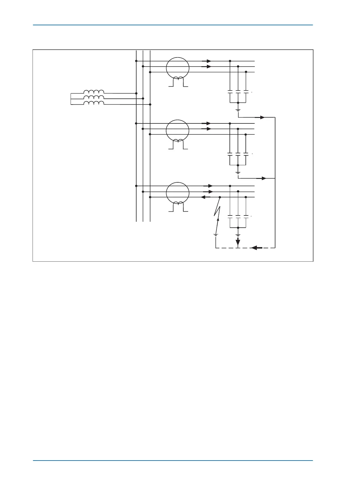
Figure 48: Current distribution in an insulated system with C phase fault
The figure above shows the relays on the healthy motor feeders see the unbalance in the charging currents for
their own feeder.
The relay on the faulted feeder, however, sees the charging current from the rest of the system (IH1 and IH2 in this
case), with its own feeders charging current (IH3) becoming cancelled out. This is further shown by the phasor
diagrams in the next figure.
P24xM Chapter 6 - Current Protection Functions
P24xM-TM-EN-2.1 121