4 APPLICATION NOTES
4.1 LOW IMPEDANCE REF PROTECTION APPLICATION
4.1.1 SETTING GUIDELINES FOR BIASED OPERATION
For this configuration, settings must be modified in the RESTRIC
TED E/F column. The REF Options setting should be
set to Lo Z REF (Low Impedance REF) protection.
To protect as much of the machine winding as possible, the differential current setting IREF>Is1 should be
adjusted to a low setting. A setting of 5% of the machine's rated current of is adequate.
If the conductors are placed reasonably concentrically within the window of the core balance current
transformers, spill current can be kept to a minimum. This low spill current and a reasonable independence of CT
ratio to full load, allows a lower fault setting than with conventional high impedance circulating current differential
schemes.
The differential current setting, IREF>Is2 should be set to 120% of the machine rated current, this is the threshold
above which the second bias setting is applied.
To provide optimum sensitivity for internal faults, the initial bias slope setting IREF>k1 should be set to 0%. And, to
provide adequate stability for external faults, the second bias slope setting IREF>ks should be set to 150%.
The above settings can be increased where low accuracy class CTs are used to supply protection.
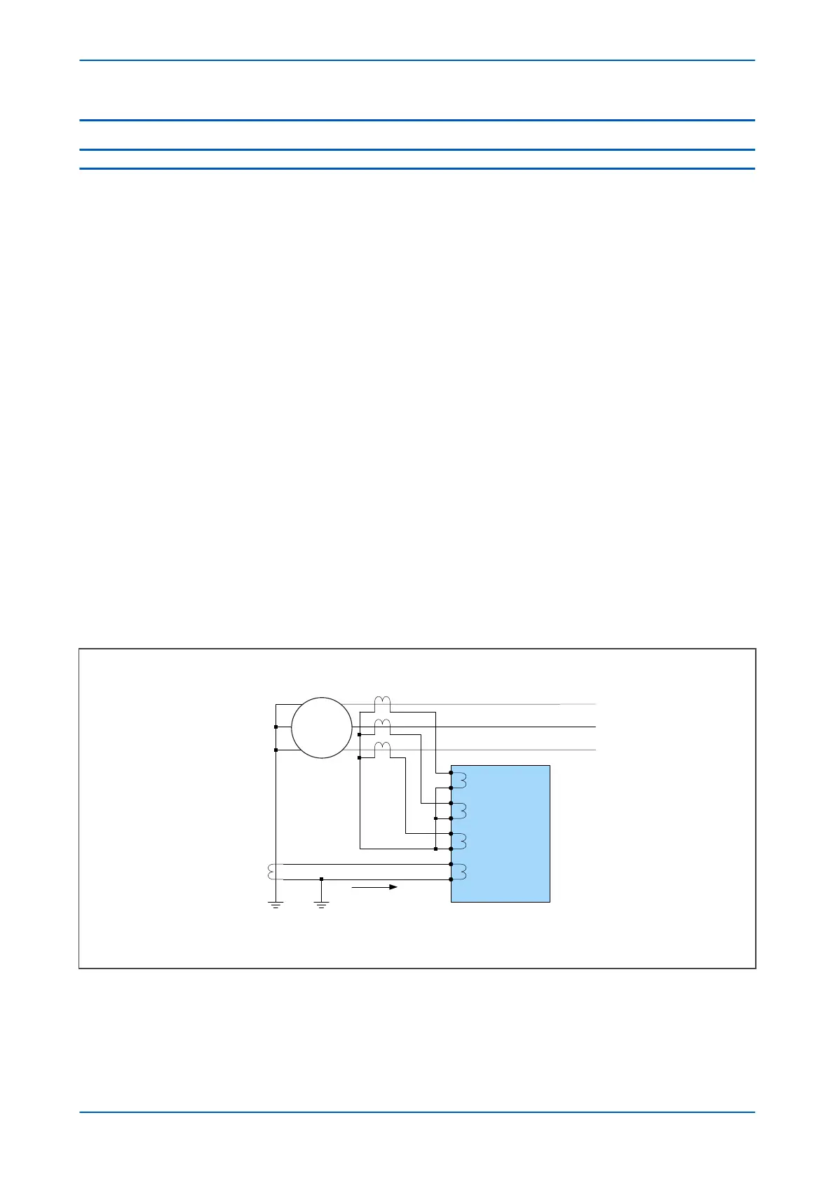
4.1.2 LOW IMPEDANCE REF SCALING FACTOR
The three line CTs are connected to the three-phase CTs, and the neutral CT is connected to the neutral CT input.
These curr
ents are then used internally to derive both a bias and a differential current quantity for use by the low
impedance REF protection. The advantage of this mode of connection is that the line and neutral CTs are not
differentially connected, so the neutral CT can also be used to provide the measurement for the Standby Earth
Fault Protection. Also, no external components such as stabilizing resistors or Metrosils are required.
IED
E00799
I
Phase A
I
Phase B
I
Phase C
I
Neutral
Phase A
Phase B
Phase C
Line CTs 1000:1
Neutral CT200:1
I
N
M
Figure 89: Low Impedance REF Scaling Factor
Another adv
antage of Low Impedance REF protection is that you can use a neutral CT with a lower ratio than the
line CTs in order to provide better earth fault sensitivity. In the bias calculation, the device applies a scaling factor
to the neutral current. This scaling factor is as follows:
P24xM Chapter 7 - Restricted Earth Fault Protection
P24xM-TM-EN-2.1 175