V01215
52A
52B
R
1
Trip Output Relay
+
ve
-ve
Opto-input 1
R2
Opto-input 2
Circuit Breaker
T
rip path
Trip coil
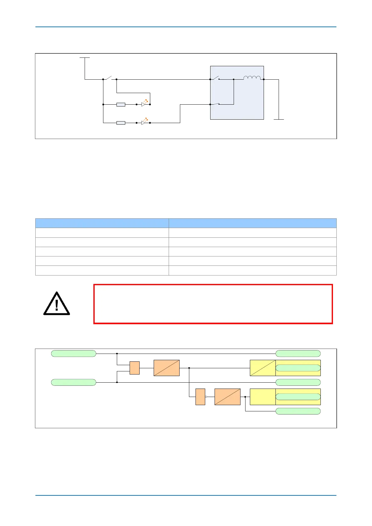
Figure 137: TCS Scheme 2
When the br
eaker is closed, supervision current passes through opto input 1 and the trip coil. When the breaker is
open current flows through opto input 2 and the trip coil. No supervision of the trip path is provided whilst the
breaker is open. Any fault in the trip path will only be detected on CB closing, after a 400 ms delay.
5.2.1 RESISTOR VALUES
As with scheme 1, optional resistors R1 and R2 can be added to prevent tripping of the CB if either opto-input is
shor
ted. The table below shows the appropriate resistor value and voltage setting for this scheme.
Trip Circuit Voltage Resistor R1 and R2
24/27 620 Ohms at 2 Watts
30/34 820 Ohms at 2 Watts
48/54 1.2 kOhms at 5 Watts
110/125 2.7 kOhms at 10 Watts
220/250 5.2 kOhms at 15 Watts
Warning:
If y
our IED has Opto Mode settings available in the OPTO CONFIG column, these
MUST be set to TCS for any corresponding Opto Inputs(s) used for Trip Circuit
Supervision.
5.2.2 PSL FOR TCS SCHEME 2
Opto Input 1
V01218
&
*Output Relay
LED
User Alarm
0
400
dropoff
straight
0
0
Latching
Opto Input 2
1
pickup
0
50
CB Aux 3ph(52-A)
CB Aux 3ph(52-B)
*NC stands for Normally Closed.
Figure 138: PSL for TCS Scheme 2
In T
CS scheme 2, both opto-inputs must be low before a trip circuit fail alarm is given.
Chapter 14 - Supervision P24xM
284 P24xM-TM-EN-2.1