Select the setting group with Nxt Grp and confirm by pr
essing Select. If neither of the cursor keys is pressed within
20 seconds of entering a hotkey sub menu, the device reverts to the default display.
3.9.2 CONTROL INPUTS
The control inputs are user-assignable functions. You can use the C
TRL I/P CONFIG column to configure the control
inputs for the hotkey menu. In order to do this, use the first setting Hotkey Enabled cell to enable or disable any of
the 32 control inputs. You can then set each control input to latched or pulsed and set its command to On/Off,
Set/Reset, In/Out, or Enabled/Disabled.
By default, the hotkey is enabled for all 32 control inputs and they are set to Set/Reset and are Latched.
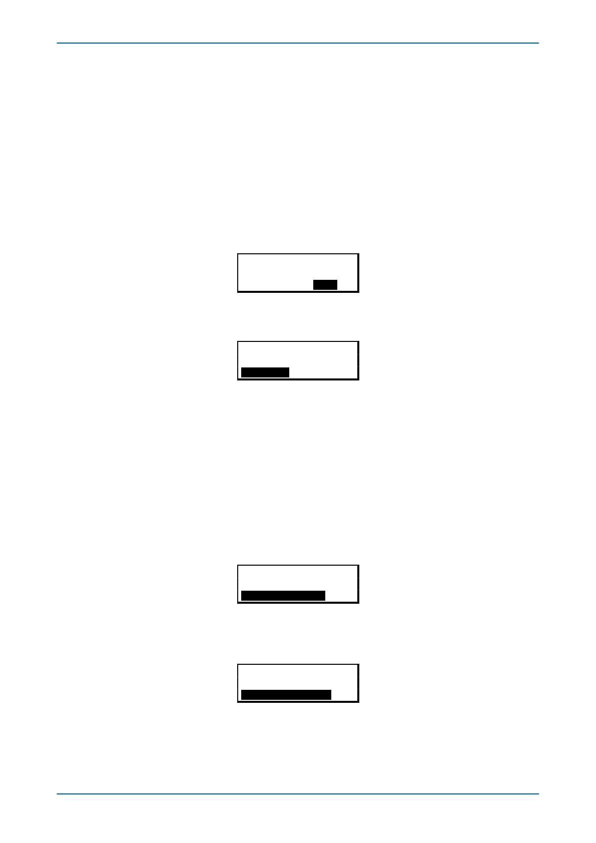
To access the hotkey menu from the default display, you press the key directly below the HOTKEY text on the LCD.
The following screen will appear.
¬User32 STG GP®
HOTKEY MENU
EXIT
Press the right cursor key twice to get to the first control input, or the left cursor key to get to the last control input.
¬STP GP User02®
Control Input 1
EXIT SET
Now you can execute the chosen function (Set/Reset in this case).
If neither of the cur
sor keys is pressed within 20 seconds of entering a hotkey sub menu, the device reverts to the
default display.
3.9.3 CIRCUIT BREAKER CONTROL
You can open and close the controlled circuit breaker with the hotkey to the right, if enabled as described above.
By default
, hotkey access to the circuit breakers is disabled.
If hotkeyaccess to the circuit breakers has been enabled, the bottom right hand part of the display will read "Open
or Close" depending on whether the circuit breaker is closed or open respectively:
For example:
Plant Reference
MiCOM
HOTKEY CLOSE
To close the circuit breaker (in this case), press the key directly below CLOSE. You will be given an option to cancel
or confirm.
Execute
CB CLOSE
Cancel Confirm
More detailed information on this can be found in the Monitoring and Control chapter.
P24xM Chapter 5 - Configuration
P24xM-TM-EN-2.1 65