such overvoltages is not too costly. Higher system voltages would normally be solidly earthed or earthed using a
low impedance.
A special case of high impedance ear
thing using a reactor occurs when the inductive earthing reactance is made
equal to the total system capacitive reactance to earth at system frequency. This practice is widely referred to as
Petersen (or resonant) Coil Earthing. With a correctly tuned system, the steady state earthfault current is zero, so
that earth faults become self-extinguishing. Such systems can, if designed, be run with one phase earthed for a
long period until the cause of the fault is identified and rectified. With the effectiveness of this method being
dependent on the correct tuning of the coil reactance to the system capacitive reactance, an expansion of the
system at any time would necessitate an adjustment of the coil reactance.
Petersen coil earthed systems are commonly found in areas where the power system consists mainly of rural
overhead lines and can be particularly beneficial in locations which are subject to a high incidence of transient
faults. The Petersen coil, for example, can extinguish transient earth faults caused by lightning strikes without the
need for outages.
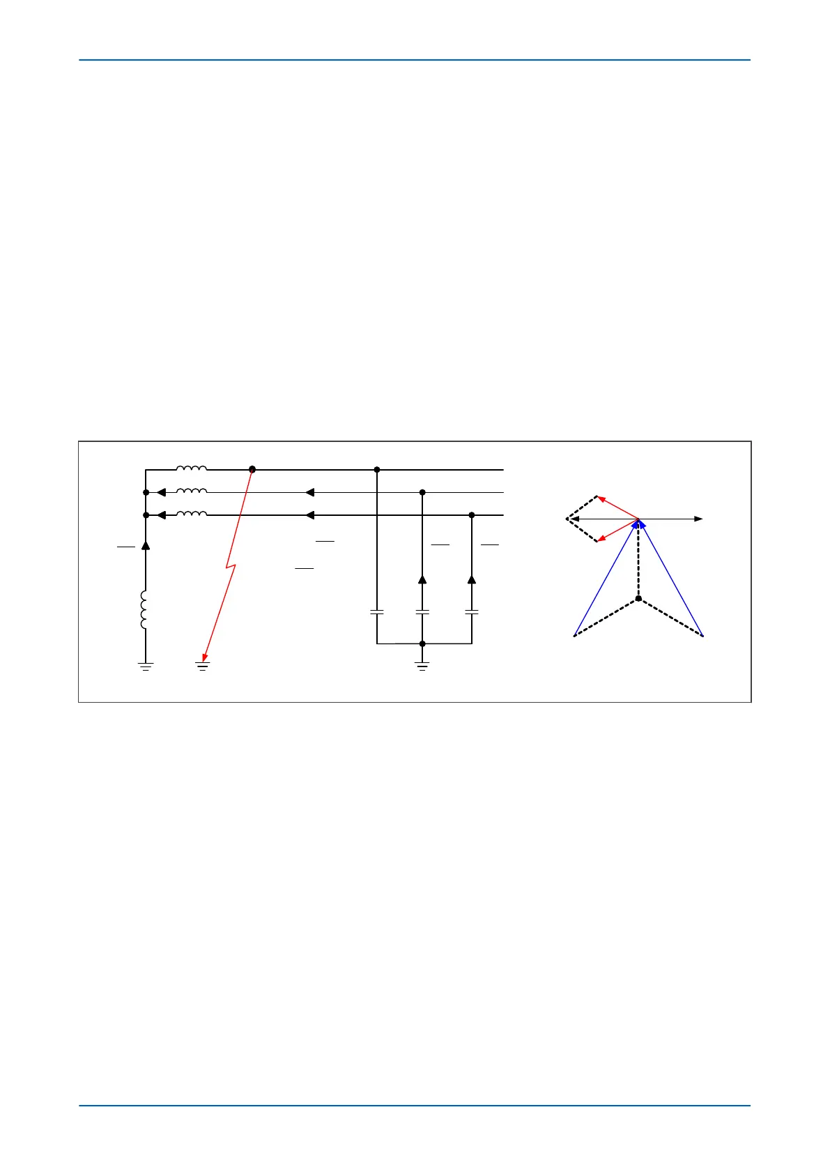
The figure below shows a source of generation earthed through a Petersen Coil, with an earth fault applied on the
A Phase. Under this situation you can see that the A phase shunt capacitance becomes short circuited by the fault.
Therefore, the calculations show that if the reactance of the earthing coil is set correctly, the resulting earth fault
current is zero.
0
AN
f B C
L
AN
B C
L
V
I I I
jX
V
if I I
jX
Source
Petersen
Coil
Current vectors for A phase fault
If
-IC
A
BC
N
-I
B
I
L
V
AB
V
AC
-I
B
-IC
(=I
L
)
(=-I
B
) (=-I
C
)
-jX
C
-jX
C
-jX
C
Figure 51: Current distribution in Petersen coil earthed system
Prior to actually applying pr
otective relays to provide earth fault protection on systems which are earthed using a
Petersen Coil, it is imperative to gain an understanding of the current distributions that occur under fault
conditions on such systems. With this information you can decide on the type of relay that may be applied,
ensuring that it is both set and connected correctly.
The figure below shows a radial distribution system having a source which is earthed using a Petersen Coil. Three
outgoing feeders are present, the lower of which has a phase to earth fault applied on the C phase.
P24xM Chapter 6 - Current Protection Functions
P24xM-TM-EN-2.1 125