2 HARDWARE ARCHITECTURE
The main components comprising devices based on the P40Agile platform are as follows:
● The housing, consisting of a fr
ont panel and connections at the rear
● The Main processor module consisting of the main CPU (Central Processing Unit), memory and an interface
to the front panel HMI (Human Machine Interface)
● An I/O board consisting of output relay contacts and digital opto-inputs
● Communication modules
● Power supply
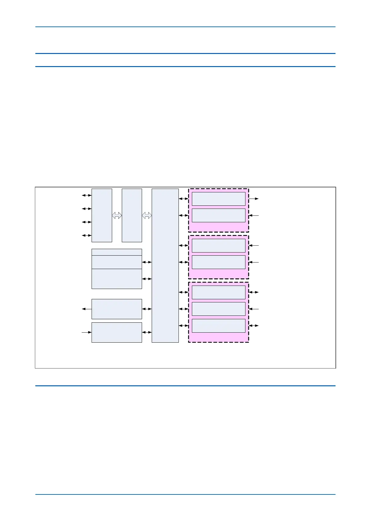
All modules are connected by a parallel data and address bus, which allows the processor module to send and
receive information to and from the other modules as required. There is also a separate serial data bus for
conveying sampled data from the input module to the CPU. These parallel and serial databuses are shown as a
single interconnection module in the following figure, which shows typical modules and the flow of data between
them.
Communications
Analogue Inputs
I/O
I
n
t
e
r
c
o
n
n
e
c
t
i
o
n
Output relay module
Opto-input module
CTs
VTs
RS485 module
Ethernet module
Keypad
L
CD
LEDs
Front port
Watchdog module
PSU module
Watchdog
c
ontacts
+ LED
Auxiliary
Supply
IRIG-B module
P
r
o
c
e
s
s
o
r
m
o
d
u
l
e
F
r
o
n
t
p
a
n
e
l
H
M
I
Output relay contacts
Digital inputs
P
ower system currents *
Power system voltages *
RS485 communication
Time synchronisation
(Optional)
Ethernet communication
(Optional)
V00200
* No VTs on current-only models. No CTs on voltage-only models
Memory
Flash memory for all
s
ettings and records
Super capacitor-backed
D
RAM
for real-time clock
Figure 3: Hardware design overview
2.1 MEMORY AND REAL TIME CLOCK
The IED contains flash memory for storing the following operational information:
● F
ault, Maintenance and Disturbance Records
● Events
● Alarms
● Measurement values
● Latched trips
● Latched contacts
Chapter 3 - Hardware Design P24xM
30 P24xM-TM-EN-2.1