4.3 DIRECTIONAL ELEMENT
If fault current can flow in both directions through a protected location, you will need to use a directional
ov
ercurrent element to determine the direction of the fault. Once the direction has been determined the device
can decide whether to allow tripping or to block tripping. To determine the direction of a phase overcurrent fault,
the device must compare the phase angle of the fault current with that of a known reference quantity. The phase
angle of this known reference quantity must be independent of the faulted phase. Typically this will be the line
voltage between the other two phases.
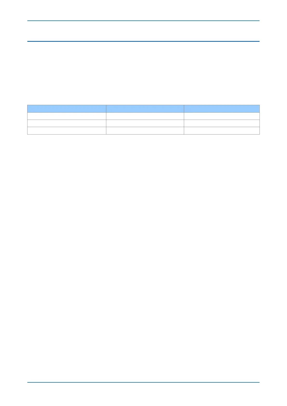
The phase fault elements of the IEDs are internally polarized by the quadrature phase-phase voltages, as shown in
the table below:
Phase of protection Operate current Polarizing voltage
A Phase IA VBC
B Phase IB VCA
C Phase IC VAB
Under system fault conditions, the fault current vector lags its nominal phase voltage by an angle depending on
the system X/R ratio
. The IED must therefore operate with maximum sensitivity for currents lying in this region. This
is achieved using the IED characteristic angle (RCA) setting. The RCA is the angle by which the current applied to
the IED must be displaced from the voltage applied to the IED to obtain maximum sensitivity.
There are two ways you can change set the characteristic and trip angles. This is controlled by the Dir Char
Setting cell in the SECURITY CONFIG column. This setting provides two options: Simple and Advanced.
In Advanced mode, the characteristic angle can be set independently for each stage. For stage 1, for example,
this would be the setting I>1 Char Angle. It is possible to set characteristic angles anywhere in the range – 180° to
+ 180°.
The opening angle of the forward or reverse trip zone can also be set independently for each stage. This allows
you to set a tripping angle of less than 180° for each stage. For stage 1, for example, you do this using the I>1 Trip
Angle setting.
In Simple mode, the angle can only be changed globally for all overcurrent stages.
A directional check is performed based on the following criteria:
Directional forward
Ð
V + RCA - 90° + (180° - tripping angle)/2 <
Ð
I <
Ð
V + RCA +90° - (180° - tripping angle)/2
Directional reverse
Ð
V + RCA - 90° - (180° - tripping angle)/2 >
Ð
I >
Ð
V + RCA +90° + (180° - tripping angle)/2
This can be best visualised with reference to the following diagram:
Chapter 6 - Current Protection Functions P24xM
96 P24xM-TM-EN-2.1

 Loading...


