Remove IN> Start
Enabled
&
CB Fail Alarm
Disabled
&
IN1>1 Start
IN1>2 Start
IN1>3 Start
IN1>4 Start
IN2>1 Start
IN2>2 Start
1 IN/SEF>Blk Start
V00649
1
IN2>3 Start
IN2>4 Start
ISEF>1 Start
ISEF>2 Start
ISEF>3 Start
ISEF>4 Start
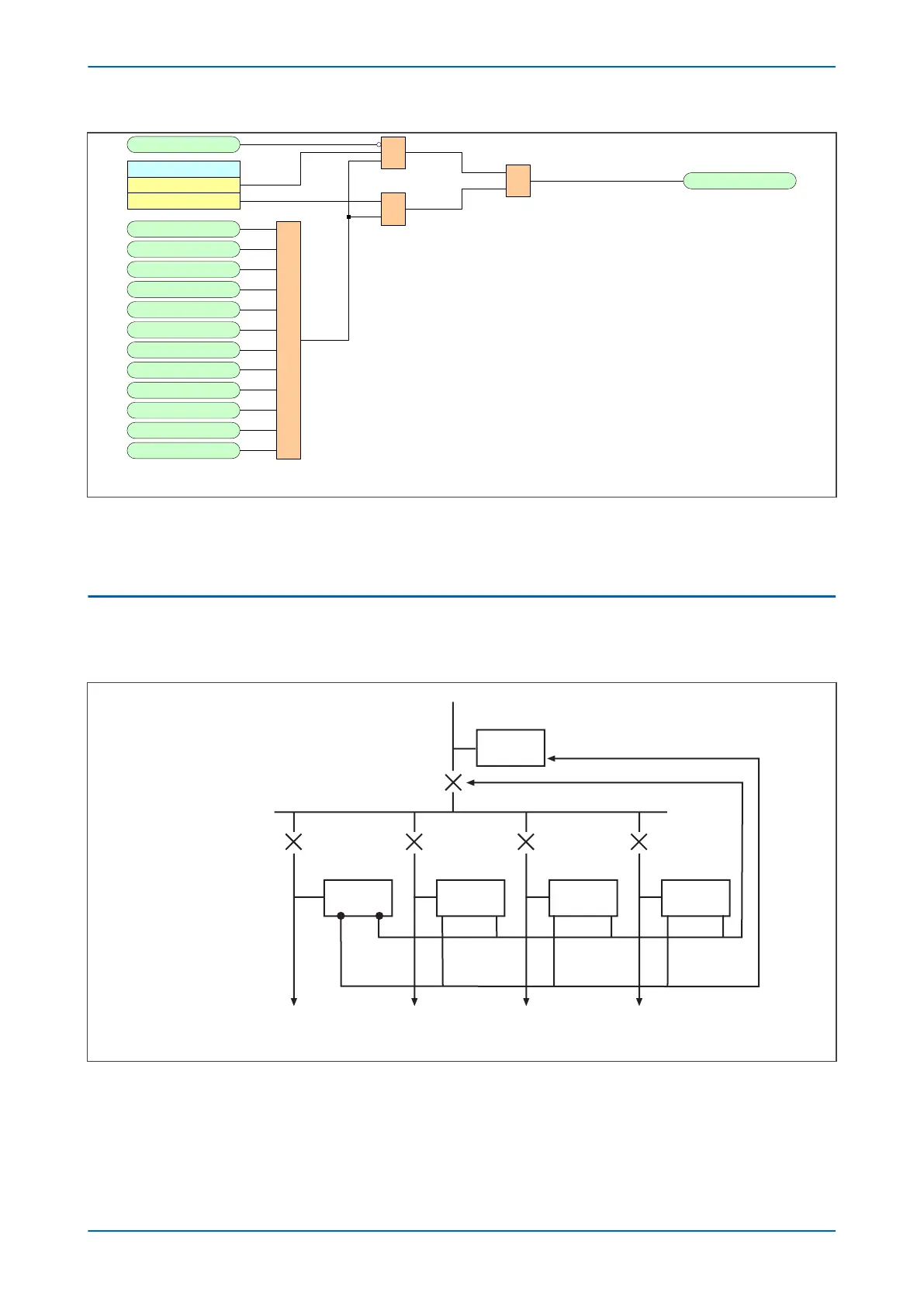
Figure 68: Blocked Earth Fault logic
The IN/SEF>Blk S
tart signal is derived from the logical OR of the phase overcurrent start outputs. This output is
then gated with the CB Fail Alarm DDB signal and the Remove IN> Start setting.
12.4 APPLICATION NOTES
12.4.1 BUSBAR BLOCKING SCHEME
E00636
IED
IED
IED
IED
IED
Incomer
Block highset element
CB fail backtrip
Feeder 4
Feeder 3
Feeder 2
Feeder 1
O/P
from
start
contact
CB
fail
backtrip
Figure 69: Simple busbar blocking scheme
Chapter 6 - Current Protection Functions P24xM
144 P24xM-TM-EN-2.1