The protection elements on the healthy feeder see the charging current imbalance for their own feeder. The
pr
otection element on the faulted feeder, however, sees the charging current from the rest of the system (IH1 and
IH2 in this case). Its own feeder's charging current (IH3) is cancelled out.
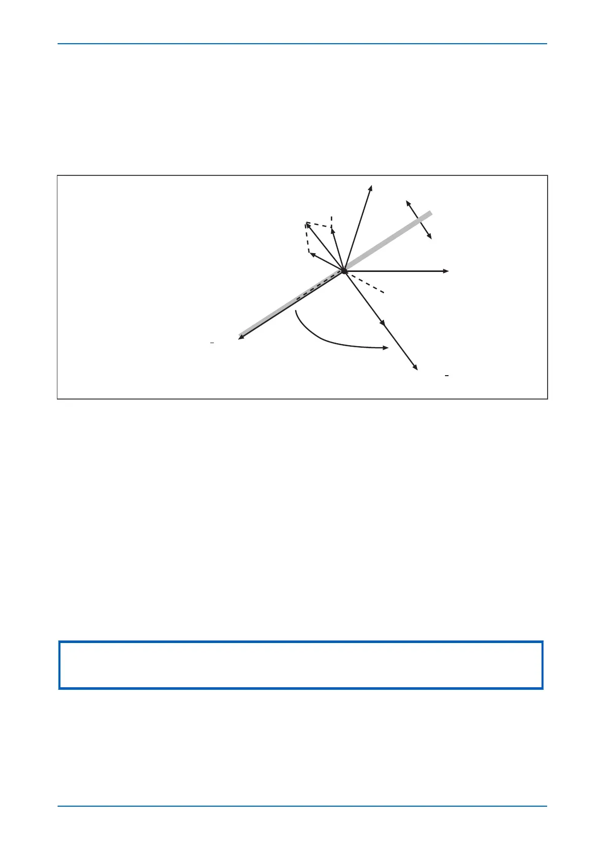
With reference to the associated vector diagram, it can be seen that the C-phase to earth fault causes the
voltages on the healthy phases to rise by a factor of √3. The A-phase charging current (Ia1), leads the resultant A
phase voltage by 90°. Likewise, the B-phase charging current leads the resultant Vb by 90°.
E00628
Restrain
Operate
Vbf
Vbpf
Vaf
Vapf
Vcpf
Ib1
IR1
Ia1
Vres
(= 3Vo)
IR3 = (IH1 + IH2)
An RCA setting of ±90º shifts the
“centre of the characteristic” to here
Figure 62: Phasor diagrams for insulated system with C phase fault
The curr
ent imbalance detected by a core balanced current transformer on the healthy feeders is the vector
addition of Ia1 and Ib1. This gives a residual current which lags the polariing voltage (–3Vo) by 90°. As the healthy
phase voltages have risen by a factor of Ö3, the charging currents on these phases are also Ö3 times larger than
their steady state values. Therefore, the magnitude of the residual current IR1, is equal to 3 times the steady state
per phase charging current.
The phasor diagram indicates that the residual currents on the healthy and faulted feeders (IR1 and IR3
respectively) are in anti-phase. A directional element (if available) could therefore be used to provide discriminative
earth fault protection.
If the polarising is shifted through +90°, the residual current seen by the relay on the faulted feeder will lie within
the operate region of the directional characteristic and the current on the healthy feeders will fall within the
restrain region.
The required characteristic angle setting for the SEF element when applied to insulated systems, is +90°. This is for
the case when the protection is connected such that its direction of current flow for operation is from the source
busbar towards the feeder. If the forward direction for operation were set such that it is from the feeder into the
busbar, then a –90° RCA would be required.
Note:
Discrimination can be provided without the need for directional control. This can only be achieved, however, if it is possible to
set the IED in excess of the charging current of the protected feeder and below the charging current for the rest of the system.
8.5.2 SETTING GUIDELINES (INSULATED SYSTEMS)
The residual current on the faulted feeder is equal to the sum of the charging currents flowing from the rest of the
system. Fur
ther, the addition of the two healthy phase charging currents on each feeder gives a total charging
current which has a magnitude of three times the per phase value. Therefore, the total imbalance current is equal
to three times the per phase charging current of the rest of the system. A typical setting may therefore be in the
Chapter 6 - Current Protection Functions P24xM
136 P24xM-TM-EN-2.1