where:
●
f = Angle betw
een the Polarising Voltage (-Vres) and the Residual Current
●
f
c
= Relay Characteristic Angle (RCA) Setting (ISEF> Char Angle)
● V
res
= Residual Voltage
● I
res
= Residual Current
● V
o
= Zero Sequence Voltage
● I
o
= Zero Sequence Current
The action of setting the PN> threshold to zero would effectively disable the wattmetric function and the device
would operate as a basic, sensitive directional earth fault element. However, if this is required, then the SEF option
can be selected from the SEF/REF Options cell in the menu.
Note:
The residual power setting, PN>, is scaled by the programmed Transformer ratios.
A further point to note is that when a power threshold other than zero is selected, a slight alteration is made to the
angular boundaries of the dir
ectional characteristic. Rather than being ±90° from the RCA, they are made slightly
narrower at ±85°.
The directional check criteria is as follows:
Directional forward: -85° < (angle(IN) - angle(VN + 180°) - RCA) < 85°
Directional reverse: -85° > (angle(IN) - angle(VN + 180°) - RCA) > 85°
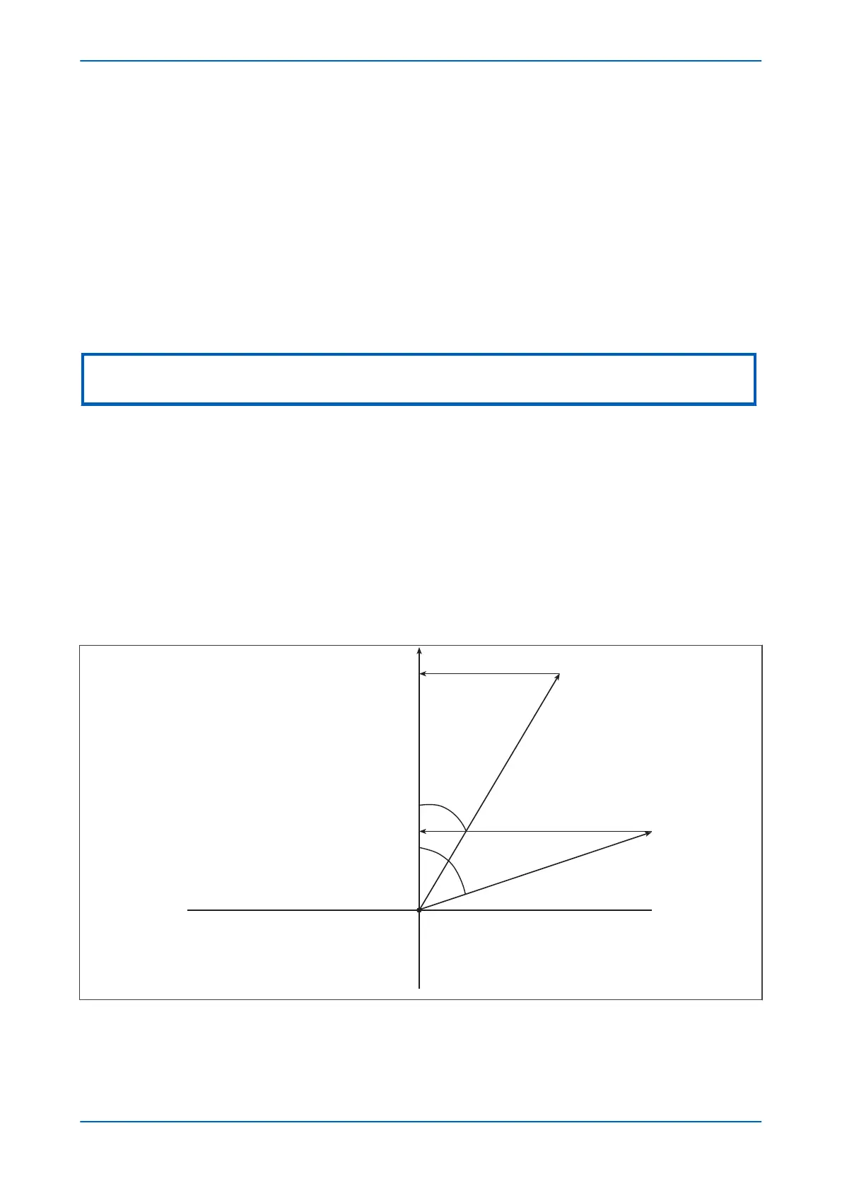
8.4.2 ICOS PHI / ISIN PHI CHARACTERISTIC
In some applications, the residual current on the healthy feeder can lie just inside the operating boundary
following a fault condition. The r
esidual current for the faulted feeder lies close to the operating boundary.
E00618
Reverse
Operation
Reverse
Operation
Forward
Operation
Polarising
V
oltage
Healthy
Feeder
Faulted
Feeder
Icos(ϕ2)
Icos(ϕ1)
ϕ1
ϕ2
Figure 59: Operating characteristic for Icos
P24xM Chapter 6 - Current Protection Functions
P24xM-TM-EN-2.1 133