Three possibilities exist for the type of protection element that you can use for sensitive earth fault detection:
● A suitably sensitiv
e directional earth fault protection element having a characteristic angle setting (RCA) of
zero degrees, with the possibility of fine adjustment about this threshold.
● A sensitive directional zero sequence wattmetric protection element having a characteristic angle setting
(RCA) of zero degrees, with the possibility of fine adjustment about this threshold.
●
A sensitive directional earth fault protection element having Icosf and Isinf characteristics.
All stages of the sensitive earth fault element can be set down to 0.5% of rated current.
8.5 APPLICATION NOTES
8.5.1 INSULATED SYSTEMS
When insulated systems are used, it is not possible to detect faults using standard earth fault protection. It is
possible to use a r
esidual overvoltage device to achieve this, but even with this method full discrimination is not
possible. Fully discriminative earth fault protection on this type of system can only be achieved by using a SEF
(Sensitive Earth Fault) element. This type of protection detects the resultant imbalance in the system charging
currents that occurs under earth fault conditions. A core balanced CT must be used for this application. This
eliminates the possibility of spill current that may arise from slight mismatches between residually connected line
CTs. It also enables a much lower CT ratio to be applied, thereby allowing the required protection sensitivity to be
more easily achieved.
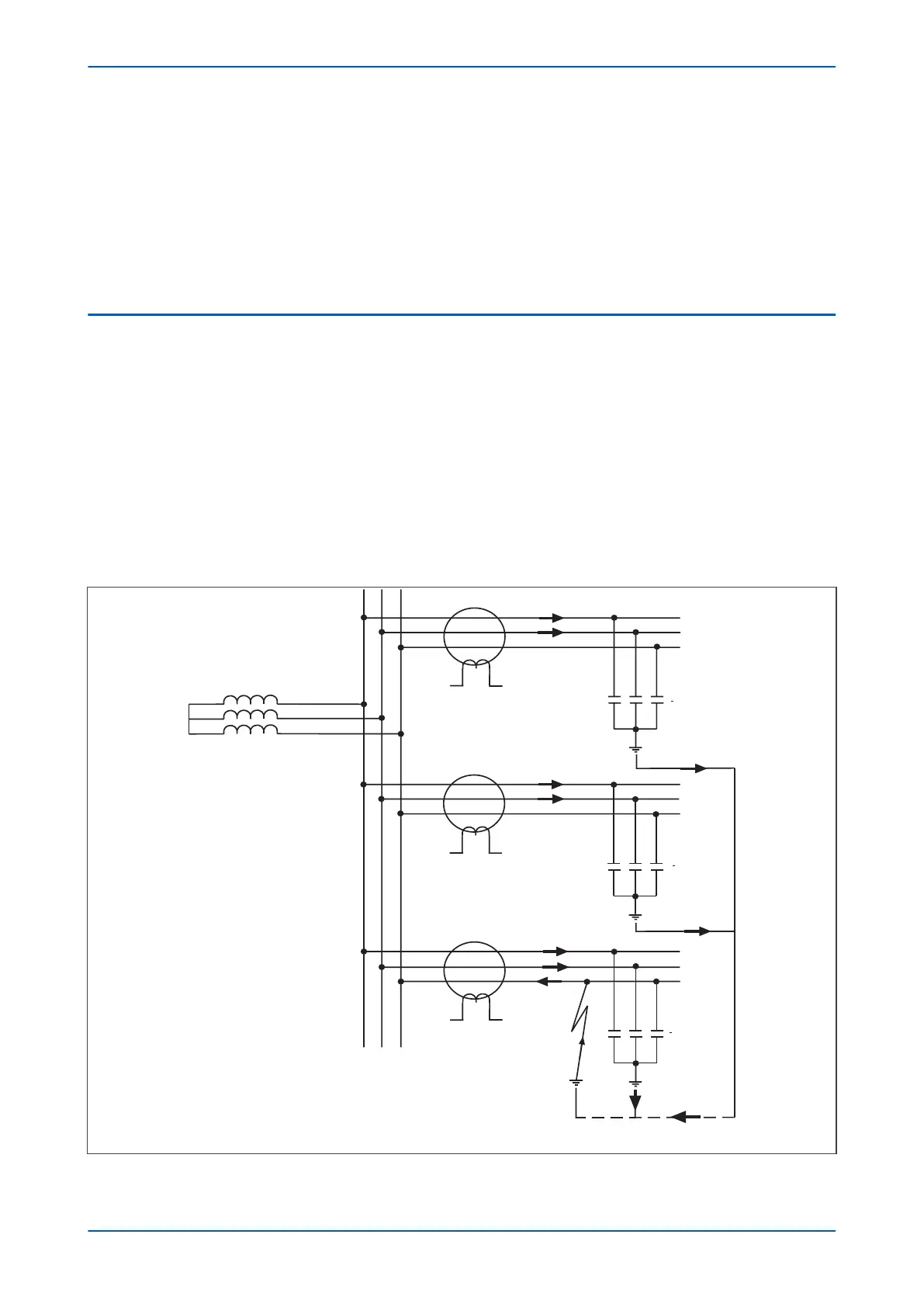
The following diagram shows an insulated system with a C-phase fault.
E00627
I
R3
IR3 = IH1 + IH2 + IH3 - IH3
IR3 = IH1 + IH2
IH3
IH1 + IH2
IH1 + IH2 + IH3
jXc3
Ia3
Ib3
IH2
jXc2
IR2
Ia2
Ib2
IH1
jXc1
IR1
Ia1
Ib1
Figure 61: Current distribution in an insulated system with C phase fault
P24xM Chapter 6 - Current Protection Functions
P24xM-TM-EN-2.1 135