E00628
Restrain
Operate
Vbf
Vbpf
Vaf
Vapf
Vcpf
Ib1
IR1
Ia1
Vres
(= 3Vo)
IR3 = (IH1 + IH2)
An RCA setting of ±90º shifts the
“centre of the characteristic” to here
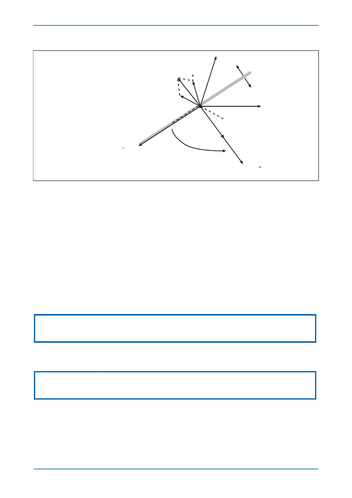
Figure 49: Phasor diagrams for insulated system with C phase fault
The diagram abov
e shows that the C phase to earth fault causes the voltages on the healthy phases to rise by a
factor of Ö3. The A phase charging currents (Ia1), is then shown to be leading the resultant A phase voltage by 90°.
Likewise, the B phase charging current leads the resultant Vb by 90°.
The unbalance current detected by a core balance current transformer on the healthy motor feeders can be seen
to be a simple vector addition of Ia1 and Ib1, giving a residual current which lies at exactly 90° lagging the residual
voltage (-3Vo). As the healthy phase voltages have risen by a factor of Ö3, the charging currents on these phases
are ·3 times larger than their steady state values. Therefore, the magnitude of residual current, IR1, is equal to 3 x
the steady state per phase charging current.
The phasor diagrams show that the residual currents on the healthy and faulted motor feeders, IR1 and IR3
respectively, are in antiphase. Therefore, a directional element can be used to provide discriminative earth fault
protection.
If the polarizing voltage of this element, Vres (equal to -3Vo), is shifted through +90°, the residual current seen by
the relay on the faulted feeder lies within the operate region of the directional characteristic and the current on the
healthy feeders falls within the restrain region.
Note:
The actual residual voltage used as a reference signal for the directional earth fault protection in the P24xM relay is internally
phase shifted by 180° and is therefore shown as -3Vo in the vector diagrams.
The required characteristic angle setting for the sensitive earth fault element when applied to insulated systems is
+90°.
Not
e:
The recommended setting corresponds to the relay being connected so that its direction of current flow for operation is from
the motor feeder into the busbar.
The P24xM relay internally derives the residual polarizing voltage for the directional earth fault element. Therefore,
either a 5-limb or thr
ee single phase VTs should be applied to drive the relay, not a VT of the three-limb design. The
former allows the passage of residual flux through the VT and permits the relay to derive the required residual
voltage. A three limb VT provides no path for the flow of residual flux, so is unsuitable. Alternatively, the relay can
be driven by a phase to phase connected VT with a broken delta winding connected to the residual voltage input.
Chapter 6 - Current Protection Functions P24xM
122 P24xM-TM-EN-2.1