V00641
a) capacitive and inductive currents with resistive components
N
b) Unfaulted line
c) Faulted line
Operate
Restrain
Zero torque line for 0° RCA
Zero torque line for 0° RCA
Operate
Restrain
I’
L
Resistive component
in grounding coil
Resistive component
in feeder
(IAH1 + IH2 + IH3)’
3V
0
BC
A
-I
H 1
- I
H2
I
L
IR1 = IH1
IR 3
I
R3
= I
F
+ I
H3
= I
L
- I
H1
- I
H12
V
res
= -3V
0
V
res
= -3V
0
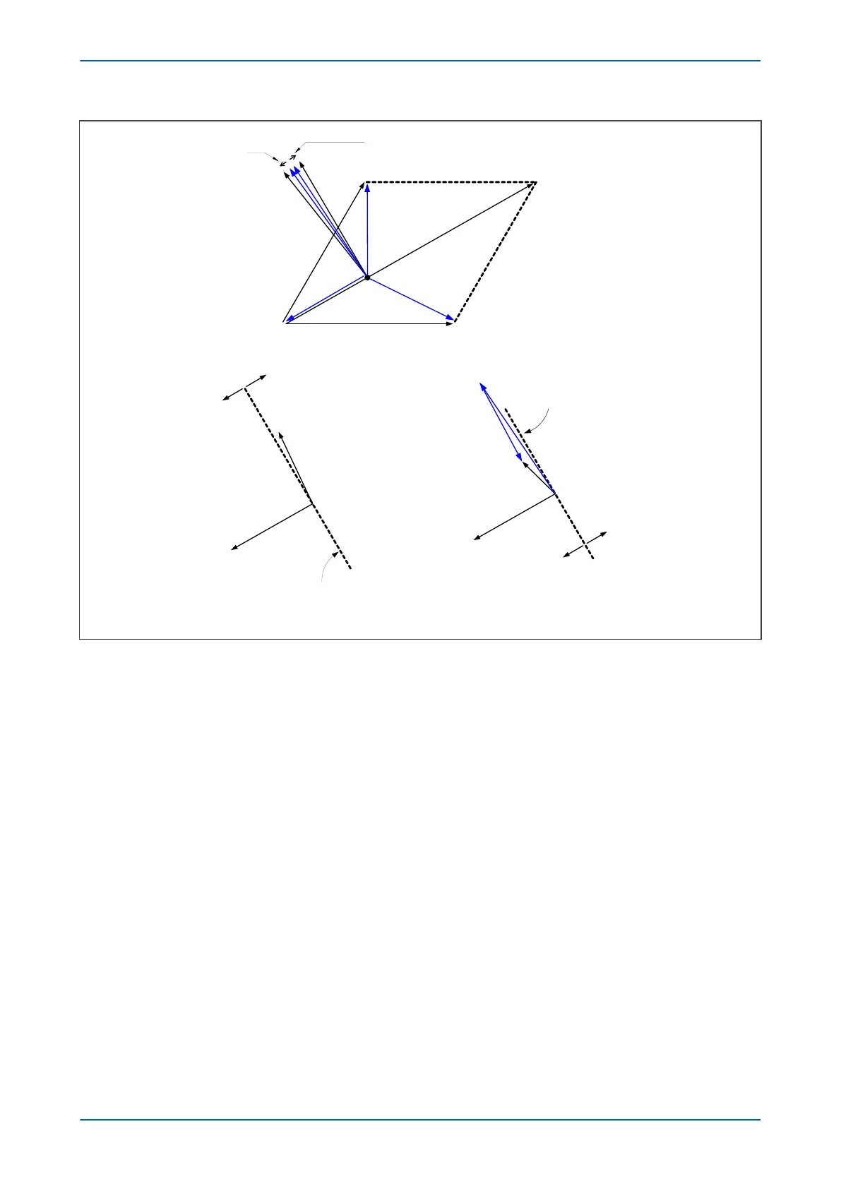
Figure 46: Phase C earth fault in Petersen Coil earthed system: practical case with resistance present
If the r
esidual voltage is used as the polarising voltage, the residual current is phase shifted by an angle less than
90° on the faulted feeder, and greater than 90° on the healthy feeders. With an RCA of 0°, the healthy feeder
residual current will fall in the ‘restrain’ area of the characteristic while the faulted feeder residual current falls in
the ‘operate’ area.
Often, a resistance is deliberately inserted in parallel with the Petersen Coil to ensure a measurable earth fault
current and increase the angular difference between the residual signals to reinforce the directional decision.
Directionality is usually implemented using a Wattmetric function, or a transient earth fault detection function
(TEFD), rather than a simple directional function, since they are more sensitive. For further information about TEFD,
refer to Transient Earth Fault Detection in the Current Protection Functions chapter.
7.5.3 SETTING GUIDELINES (COMPENSATED NETWORKS)
The directional setting should be such that the forward direction is looking down into the protected feeder (away
fr
om the busbar), with a 0° RCA setting.
For a fully compensated system, the residual current detected by the relay on the faulted feeder is equal to the coil
current minus the sum of the charging currents flowing from the rest of the system. Further, the addition of the two
healthy phase charging currents on each feeder gives a total charging current which has a magnitude of three
times the steady state per phase value. Therefore, for a fully compensated system, the detected unbalanced
current is equal to three times the per phase charging current of the faulted circuit. A typical setting may therefore
be in the order of 30% of this value, i.e. equal to the per phase charging current of the faulted circuit. In practise,
the exact settings may well be determined on site, where system faults can be applied and suitable settings can
be adopted based on practically obtained results.
Chapter 6 - Current Protection Functions P24xM
118 P24xM-TM-EN-2.1