7.2 NON-DIRECTIONAL EARTH FAULT LOGIC
V04003
Not applicab le for IN1
IN2>1 Timer Blk
IN2>1 Start
IN2>1 Trip
CTS Block
IN2> Blocking
2H Blocks IN>2
IN2>1 Current
&
IDMT/DT
Timer Settings
&
&
IN2> Inhibit
I2H Any Start
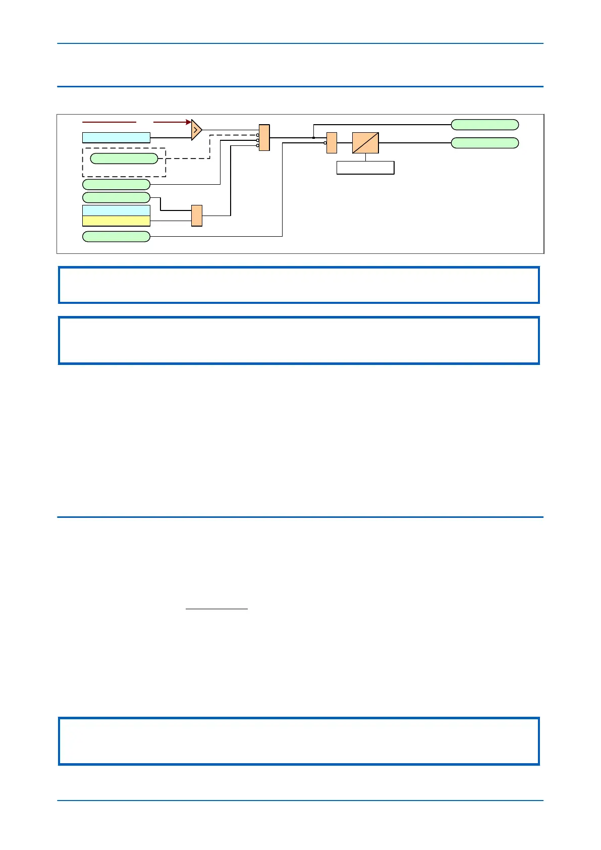
Note: This diagram shows the logic for IN2 (derived earth fault). The logic
for IN1 (measured earth fault) follows the same principles, but with no CTS
blocking.
This diagram does not show all st ages. Ot her stages f ollow similar
princip les.
IN2
Note:
Non-dir
ectional EF logic (single stage)
Note:
1 If a CLP condition exists
, the I>(n) Current Set threshold is taken from the COLD LOAD PICKUP column
2 The CTS blocking is not applicable for IN1, however this can be achieved using the PSL
The Earth Fault current is compared with a set threshold (IN1>(n) Curr
ent) for each stage. If it exceeds this
threshold, a Start signal is triggered, providing it is not blocked. This can be blocked by the second harmonic
blocking function, or an Inhibit Earth Fault DDB signal.
The autoreclose logic can be set to block the Earth Fault trip after a prescribed number of shots (set in
AUTORECLOSE column). This is achieved using the AR Blk Main Prot setting. this can also be blocked by the
relevant timer block signal IN1>(n)TimerBlk DDB signal.
Earth Fault protection can follow the same IDMT characteristics as described in the Overcurrent Protection
Principles section. Please refer to that section for details of IDMT characteristics.
The diagram and description also applies to the Earth Fault 2 element (IN2).
7.3 IDG CURVE
The IDG curve is commonly used for time delayed earth fault protection in the Swedish market. This curve is
av
ailable in stage 1 of the Earth Fault protection.
The IDG curve is represented by the following equation:
t
I
IN Setting
op e
= −
>
5 8 1 35. . log
where:
t
op
is the operating time
I is the measur
ed current
IN> Setting is an adjustable setting, which defines the start point of the characteristic
Note:
Although the start point of the characteristic is defined by the "ΙN>" setting, the actual current threshold is a different setting
called "IDG Ιs". The "IDG Ιs" setting is set as a multiple of "ΙN>".
Chapter 6 - Current Protection Functions P24xM
110 P24xM-TM-EN-2.1