7 POSITIVE SEQUENCE OVERVOLTAGE PROTECTION
7.1 POSITIVE SEQUENCE OVERVOLTAGE IMPLEMENTATION
Positive Sequence Overvoltage Protection is implemented under the P
OS SEQ O/V heading in the VOLT
PROTECTION Voltage column of the relevant settings group.
The product provides two stages of Positive Sequence Overvoltage protection with independent time delay
characteristics.
Stage 1 provides a choice of operate characteristics, where you can select between:
● An IDMT characteristic
● DT (Definite Time)
You set this using the V1>1 Function cell.
The IDMT characteristic is defined by the following formula:
t = K/( M-1)
where:
● K = Time multiplier setting
● t = Operating time in seconds
● M = Measured voltage / IED setting voltage
There is no Timer Hold facility for Positive Sequence Overvoltage.
Stage 2 can have definite time characteristics only. This is set in the V1>2 status cell.
Two stages are included in order to provide multiple output types, such as alarm and trip stages.
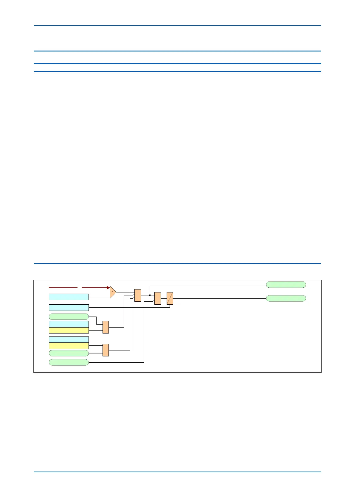
7.2 POSITIVE SEQUENCE OVERVOLTAGE LOGIC
V00817
V1
V1>1 Voltage Set
&
V1>1 Time Delay
V1>1 Trip
V1>1 Start
&
V1>1 Timer Block
V 1>1 Poledead Inh
Enabled
All Poles Dead
&
Note: This diagram does not show all stages . Other stages follow similar principles.
VTS Fast Block only applies for directional models .
VTS Fast Block
&
VTS Blocks 1
Enabled
Figure 105: Positive Sequence Overvoltage logic
P24xM Chapter 10 - Voltage Protection Functions
P24xM-TM-EN-2.1 217