6.2 FREQUENCY-SUPERVISED R.O.C.O.F LOGIC
Stage 1
V00853
Stg1 df/dt+t Trp&
Enabled
&
1
V df/dt
f+df /dt 1 df/dt X
-1
df/dt Avg .Cycles
Frequency
determination
f+df/ dt 1 freq
Freq Avg.Cycles
V
Frequency
averaging
X
-1
Frequency
determination
Adv Freq Inh
Freq Not Found
V<B Status
Enabled
UV Block
1
Stg1 Block
1
Freq High
Freq Low
1
f+df/dt 1 Status
Both
Positive
Negative
1
1
Disabled
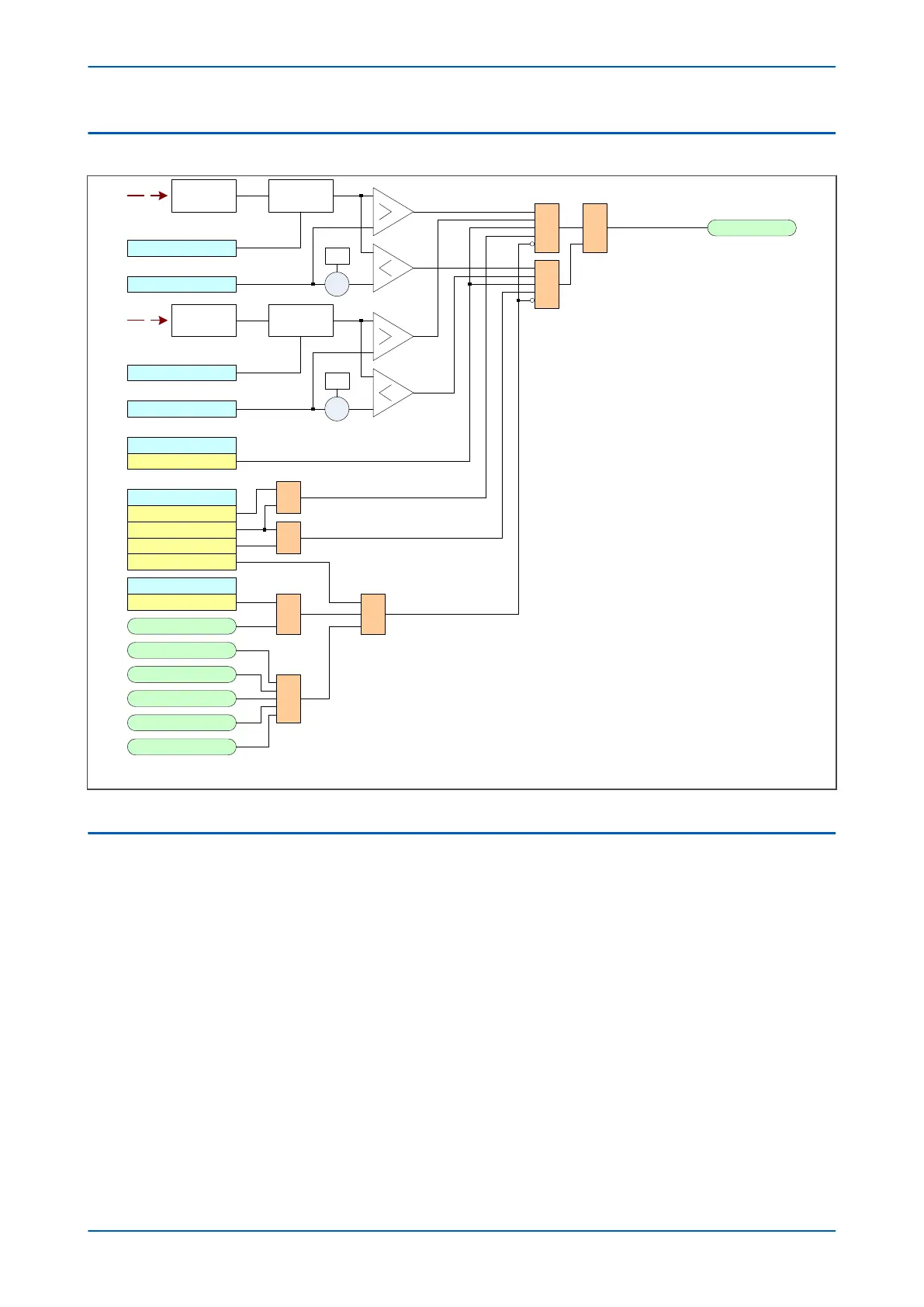
Note: This diagram does not show all stages . Other stages follow similar principles.
Figure 116: Frequency-supervised rate of change of frequency logic (single stage)
6.3 APPLICATION NOTES
6.3.1 FREQUENCY-SUPERVISED R.O.C.O.F EXAMPLE
In the load shedding scheme below, we assume that for falling frequency conditions, the system can be stabilised
at fr
equency f2 by shedding a stage of load. For slow rates of decay, this can be achieved using the
underfrequency protection element set at frequency f1 with a suitable time delay. However, if the generation
deficit is substantial, the frequency will rapidly decrease and it is possible that the time delay imposed by the
underfrequency protection will not allow for frequency stabilisation. In this case, the chance of system recovery
will be enhanced by disconnecting the load stage based on a measurement of rate of change of frequency and
bypassing the time delay.
Chapter 11 - Frequency Protection Functions P24xM
232 P24xM-TM-EN-2.1