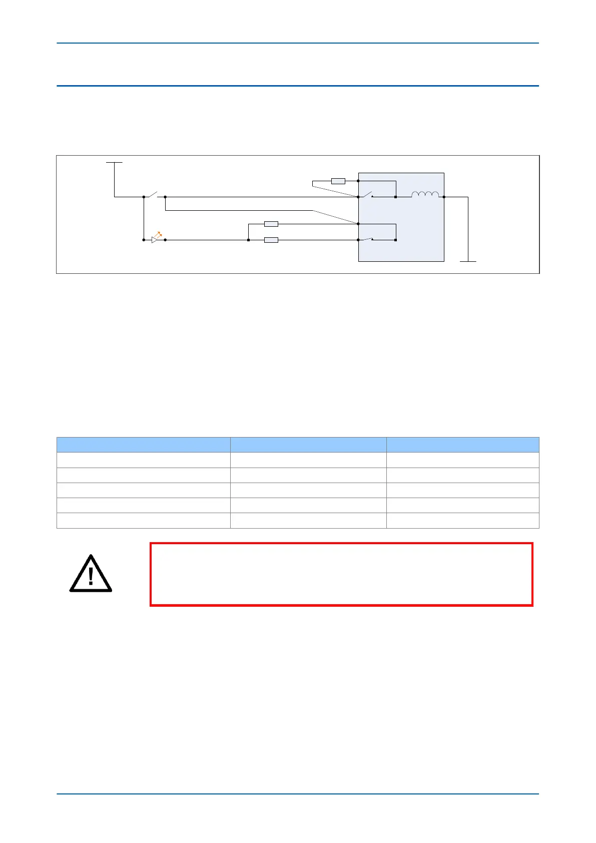
5.3 TRIP CIRCUIT SUPERVISION SCHEME 3
TCS Scheme 3 is designed to provide supervision of the trip coil with the breaker open or closed. It provides pre-
closing super
vision of the trip path. Since only one opto-input is used, this scheme is not compatible with latched
trip contacts. If you require CB status monitoring, further opto-inputs must be used.
V01216
52A
52B
Output Relay
+
ve
-ve
Opto-input
Circuit Breaker
R3
R2
R1
Trip path
T
rip coil
Figure 139: TCS Scheme 3
When the CB is closed, super
vision current passes through the opto-input, resistor R2 and the trip coil. When the
CB is open, current flows through the opto-input, resistors R1 and R2 (in parallel), resistor R3 and the trip coil. The
supervision current is maintained through the trip path with the breaker in either state, therefore providing pre-
closing supervision.
5.3.1 RESISTOR VALUES
As with TCS schemes 1 and 2, resistors R1 and R2 are used to prevent false tripping, if the opto-input is
accidentally shor
ted. However, unlike the other two schemes, this scheme is dependent on the position and value
of these resistors. Removing them would result in incomplete trip circuit monitoring. The table below shows the
resistor values and voltage settings required for satisfactory operation.
Trip Circuit Voltage Resistor R1 and R2 Resistor R3
24/27 620 Ohms at 2 Watts 330 Ohms at 5 Watts
30/34 820 Ohms at 2 Watts 430 Ohms at 5 Watts
48/54 1.2 kOhms at 5 Watts 620 Ohms at 10 Watts
110/125 2.7 kOhms at 10 Watts 1.5 k Ohms at 15 Watts
220/250 5.2 kOhms at 15 Watts 2.7 k Ohms at 25 Watts
Warning:
If y
our IED has Opto Mode settings available in the OPTO CONFIG column, these
MUST be set to TCS for any corresponding Opto Inputs(s) used for Trip Circuit
Supervision.
P24xM Chapter 14 - Supervision
P24xM-TM-EN-2.1 285