5.3 APPLICATION NOTES
5.3.1 SETTING GUIDELINES
Considerable care should be taken when setting this element because it is not supervised by a frequency setting.
Setting of the time delay or incr
easing the number of df/dt averaging cycles will improve stability but this is traded
against reduced tripping times.
It is likely that this element would be used in conjunction with other frequency based protection elements to
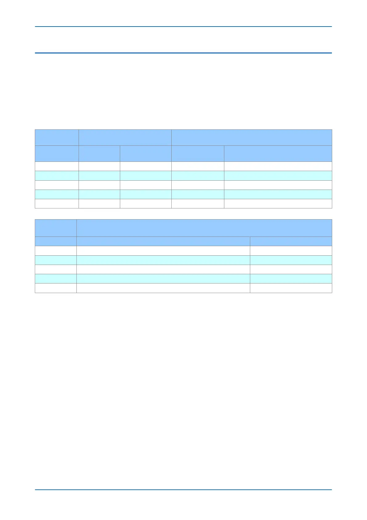
provide a scheme that accounts for severe frequency fluctuations. An example scheme is shown below:
Frequency "f+t [81U/81O]" Elements
Frequency Supervised Rate of Change of Frequency "f+df/dt
[81RF]" Elements
Stage
Frequency
Setting (Hz)
Time Setting (Sec.)
Frequency Setting
(Hz)
Rate of Change of Frequency Setting (Hz/
Sec.)
1 49 20 49.2 1.0
2 48.6 20 48.8 1.0
3 48.2 10 48.4 1.0
4 47.8 10 48.0 1.0
5 - - - -
Stage
Rate of Change of Frequency
"df/dt+t [81R]" Elements
Rate of Change of Frequency Setting (Hz/Sec.) Time Setting (Sec.)
1 - -
2 - -
3 -3.0 0.5
4 -3.0 0.5
5 -3.0 0.1
In this scheme, tripping of the last two stages is accelerated by using the independent rate of change of frequency
element
. If the frequency starts falling at a high rate (> 3 Hz/s in this example), then stages 3 & 4 are shed at
around 48.5 Hz, with the objective of improving system stability. Stage 5 serves as an alarm and gives operators
advance warning that the situation is critical.
Chapter 11 - Frequency Protection Functions P24xM
230 P24xM-TM-EN-2.1