5 NEGATIVE SEQUENCE OVERVOLTAGE PROTECTION
Where an incoming feeder is supplying rotating plant equipment such as an induction motor, correct phasing and
balance of the supply is essential. Incorr
ect phase rotation will result in connected motors rotating in the wrong
direction. For directionally sensitive applications, such as elevators and conveyor belts, it is unacceptable to allow
this to happen.
Imbalances on the incoming supply cause negative phase sequence voltage components. In the event of incorrect
phase rotation, the supply voltage would effectively consist of 100% negative phase sequence voltage only.
5.1 NEGATIVE SEQUENCE OVERVOLTAGE IMPLEMENTATION
Negative Sequence Overvoltage Protection is implemented in the NEG SEQUENCE O/V column of the r
elevant
settings group.
The device includes one Negative Phase Sequence Overvoltage element with two stages. Only Definite time is
possible.
This element monitors the input voltage rotation and magnitude (normally from a bus connected voltage
transformer) and may be interlocked with the motor contactor or circuit breaker to prevent the motor from being
energised whilst incorrect phase rotation exists.
The element is enabled using the V2>1 status and V2>2 status cells.
5.2 NEGATIVE SEQUENCE OVERVOLTAGE LOGIC
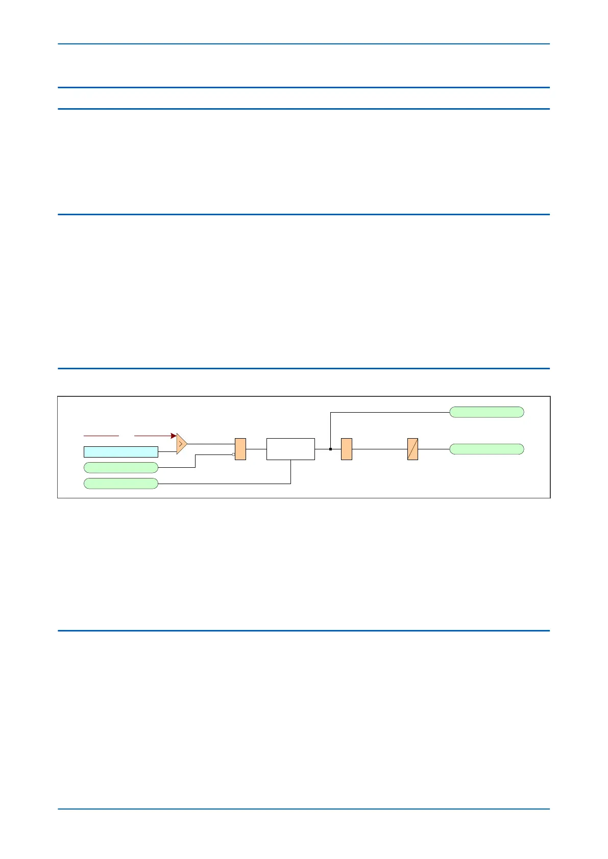
V2>1 Voltage Set
V2>1 Trip
V00818
V2>1 Start
V2>1 Accelerate
VTS Fast Block
Start
Counter
DT
&&
V2
Note: This diagram does not show all stages . Other stages follow similar principles.
VTS Fast Block only applies for directional models .
Figure 103: Negative Sequence Overvoltage logic
The Negative Voltage Sequence Overvoltage module detects when the voltage magnitude exceeds a set
threshold. When this happens, the comparator output Overvoltage Module produces a Start signal (e.g. for stage
1: V2>1 Start), which signifies the "Start of protection". This can be blocked by a VTS Fast block signal. This Start
signal is applied to the DT timer module. The output of the DT timer module is the trip signal which is used to drive
the tripping output relay.
The V2>1 Accelerate signal accelerates the operating time of the function, by reducing the number of confirmation
cycles needed to start the function. At 50 Hz, this means the protection Start is reduced by 20 ms.
5.3 APPLICATION NOTES
5.3.1 SETTING GUIDELINES
The primary concern is usually the detection of incorrect phase rotation (rather than small imbalances), therefore a
sensitiv
e setting is not required. The setting must be higher than any standing NPS voltage, which may be present
due to imbalances in the measuring VT, device tolerances etc.
A setting of approximately 15% of rated voltage may be typical.
Chapter 10 - Voltage Protection Functions P24xM
214 P24xM-TM-EN-2.1